CNC Part5 - Macros
This is the 5th part of my portal milling machine sequel. It focuses on handy accessories that make your life as a CNC operator easier, and can lead to more quick and accurate milling results.
- Part 1: Thoughts about CNCs in general and machine selection
- Part 2: CNC Electronics build
- Part 3: CNC Machine build
- Part 4: CNC Setup
Overview
This article is about Macros for the CNC that help automate certain repeating operations. It will both cover basic and more sophisticated Macros for many purposes like automatic Z-zeroing, tool length measurement, or tool changes. It will touch some G-code commands and try to help you gain more confidence in your machine.
Disclaimer
The following subroutines have been written for RS274 NGC interpreter. I have validated them with EdingCNC as that is the CNC software I happen to be using. I have taken some inspiration from the macro file that both Sorotec and EdingCNC provide along with their machines.
As you might have different Hardware and Software distributors for your machine, these routines might not fit 100%. My intention was more to explain what’s happening in them than to provide a 1-by-1 copy paste template.
You might want to skip reading this article if your jobs are simple enough so you never felt the need to dive into CNC subroutines or in case your setup is 100% complete and you’ll never touch it again.
So what is a Macro?
A Macro or subroutine is a collection of instructions written for the CNC interpreter to perform actions. They are often used to automate recurring operations. On my machine, such a macro starts with a SUB command and ends with an ENDSUB. They likely include branching logic and G-code commands to have the machine do things or even show user dialogs to get the operator’s input.
On my machine, all macros are residing in a single file called macro.cnc that my CNC software will read on startup so it can be executed. Some of the software’s buttons even directly call macros from this file, e.g. for homing.
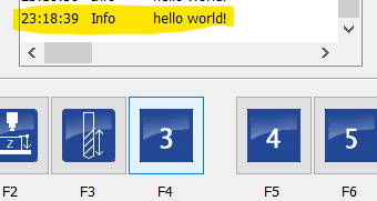 To demonstrate that this file matters a lot, close your CNC software and open the
 macro.cnc document with a text editor. Search for Sub user_9 (it should be a routine that doesn’t do relevant stuff), remove its contents and add the line MSG "hello world!" to it. Save your work, start the CNC software, and in the user menu, press button 9 - Voilà!
Starters: A simple macro to detect Tool Length Sensor status
Let’s get going and connect the newly-grown knowledge about macros to a useful example.
The tool length sensor
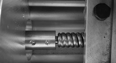
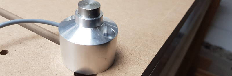 A tool length sensor is a device connected to an input of the CNC machine that triggers when touched (e.g. by a tool tip). There are many different designs available, ranging from a very simple microswitch with an enclosure and touch button to high-precision heavy steel sensors with automatic air purge operation to make sure the sensor’s surface is clean.
The tool length sensor is either mounted at the machine bed, on top of the spoilboard, or just placed at another fixed position on the machine. Mine is a very simple switch that I can put on any place of my machine. It has a claimed repeatability of 10µm.
Anyways, the actual magic is done in the CNC software.
Macro task
I want the macro to check whether the tool length sensor is operational (and not stuck). So I verify that the sensor switch’s status is “not triggered” - normally closed. If it was triggered, this could mean the sensor is stuck pushed (happened to me already) or has a broken sensor wire (didn’t happen so far), or just that the sensor is not connected to the machine at all.
Macro code
SUB is_sensor_ok
    IF [sensorStatus == triggered] ;# 5068 == 0 (normally closed)
        DLGMSG "Tool length sensor not connected or already triggered - please check"
        IF [dialogButton == 1]
            IF [sensorStatus == triggered]
                ERRMSG "Tool length sensor input still unexpected - aborting"
            ENDIF
        ELSE
            ERRMSG "User abort."
        ENDIF
    ENDIF
ENDSUB
The Macro’s name is is_sensor_ok. I’m checking sensor status and present a dialog message in case something is wrong here. Once the operator presses “OK”, I’m assuming that the problem has been taken care of and try again. If it is still triggered, I’ll abort the routine.
This Macro can be found in all sections below where I need the tool length sensor to measure something - It serves as a guard to not accidentally destroy my machine, the sensor, or the workpiece by interpreting wrong input.
Variable naming
The RS274/NGC language is old. I mean really old. Its first version was released in the late 1950’s. No wonder its parameters (#1 - #5399 is the allowed range) are all numeric both in naming and in the values they are able to store. No type system (like strings, int etc.) and no handy naming that makes understanding a parameter easy like sensorStatus.
It will just be #5068 and you’ll have to remember yourself that the CNC software manufacturer selected this variable to flag the tool length sensor’s status, and that it is boolean with 0 = not triggered and 1 = triggered.
To make the macro code as readable and comprehensible as possible, I refrain from using numerical parameter names in this article. A translation table can be found at the bottom for your convenience.
Using the tool length sensor to get workpiece surface (Z=0)
With this method, you don’t need to manually zero in workpiece surfaces by lowering Z-axis until the tool slightly scratches the surface and then setting workpiece coordinates.
 Once the Macro is programmed and set up, just place the tool length sensor on top of your workpiece and jog your machine so it is placed directly above the sensor (not touching yet). Then start the macro. Your machine will now automatically lower its Z-axis slowly until the sensor switches. It will then reverse very slowly until the sensor untriggers. This point is then taken to determine Z-0 which is then set automatically.
Prerequisites
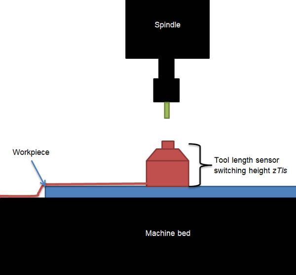
What we need before we can write the macro is the tool length sensor’s Z-position zTls at its switching point from being triggered to not triggered. I measured mine with a caliper and noted it down. We need this value so the machine can subtract it from the Z-height when touching off to yield the workpiece surface’s height.
Also, it is important to know how the switch is connected to the machine. The preferred way is “normally closed”, so the switch opens when triggered: triggered = 0. This is the more safe application because a broken wire or lost connection is detected automatically as the circuit breaks.
We’ll also have to determine touch probe forward feed and reverse feed, e.g. touch = 100mm/min, rev = 10mm/min.
The macro also features a more elaborate part: When Z-0 is about to be measured, but tool length is not known, the machine is able to store current position posX, posY in repositioning variables so that the get_tool_length macro can be called directly from here, and later repositionTo to where workpiece Z-0 is being measured.
The subroutine “Z-zero detection”
After switching the spindle off, the program will lower the machine’s Z-axis until it touches the tool length sensor (or until it has travelled down, spindle nose almost touchting the sensor where it would abort, claiming it didn’t find the sensor) via command G38.2. When triggered, it will reverse carefully until the sensor is released. This point is then saved as the new coordinate offset for the Z-axis via G92.
Code
before we start, make sure we’re in the correct state. Tool length should already be determined so future tool changes won’t require re-touching off Z-zero. Plus, we should know that the sensor is properly connected.
SUB measure_workpiece_z0
    IF ![toolLengthStat]
        DLGMSG "WARNING - Please first measure tool length!"
        IF [dialogButton == 1]
            xPosReposition = xPos
            yPosReposition = yPos
            repositionTo = 1
            GOSUB get_tool_length
        ENDIF
    ENDIF

    GOSUB is_sensor_ok              ;# Check if tool length sensor status is OK
Let’s now program the actual routine by asking the operator whether Z-zeroing shall be performed now. When the CNC runs in simulator mode (without actual hardware connected), Z-zeroing won’t work so we also have to check this.
    DLGMSG "Start Z-Zeroing?"
    IF [dialogButton == 1] AND [operatingMode != simulator]
        M5                          ;#Switch spindle off
        M9                          ;#Switch coolant off
        G53 G38.2 Z[zSpindleTip + 5] F[touch]
                                    ;# G38.2 = touch toward probe, stop on contact, flag error on fail
                                    ;# fail = 5mm before touching spindle tip
        IF [probeOk == 1]           ;# #5067 == 1 : G38.2 command success
            G38.2 G91 Z20 F[rev]    ;# now reverse slowly to find untrigger point (max. 20mm up)
            G90                     ;# back to absolute coordinates
            IF [probeOk == 1]
                G00 Z[zTouched]     ;# #5063 Go to Z-axis's probe point
                G92 Z[zTls]         ;# Set Z-axis's coordinate offset (0) to tool length sensor's height
                G00 Z[zTls + 5]     ;# clear sensor
            ELSE
                ERRMSG "Could not locate sensor untrigger point."
            ENDIF
        ELSE
            DLGMSG "Could not locate sensor trigger point. Retry?"
            IF [dialogButton == 1]
                GOSUB measure_workpiece_z0
            ELSE
                ERRMSG "User abort."
            ENDIF
    ENDIF
ENDSUB
Executing the Get tool length macro on my machine
In this video, the machine is configured to return to XY zero when tool measurement has been completed. It would behave the same if I had the tool length measured after a tool change.
Tool change
When there is no macro for tool changes, the machine will pause its job and wait until you manually jogged it to where you perform the tool change, and requires that you re-zero the workiece’s Z0 position due to possibly changed tool length before continuing the job.
This task can easily be automated and the following section guides you how to write a Macro for this.
Prerequisites
An optional flag getToolLength could be configuring the tool change macro’s behavior - whether every tool’s length should be measured after a tool change or not. If you have an automatic tool changer, you might not need this to happen.
The following additional parameters are also needed
- X-Position
xToolChgwhere the tool change takes place (for me it’sxToolChg = xPosTls) - Y-Position
yToolChgwhere the tool change takes place (for me it’syToolChg = yPosTls) - re-use
zSafetyfromget_tool_lengthmacro newToolNumberto indicate the requested tool from G-code (or for manual input)currToolNumberto indicate the “old” tool to be replacedtoolChangeDonehelper flag to indicate whether a tool change has taken place yet
The subroutine “Change Tool”
The following steps are being performed by the macro when a tool change is indicated either by command M06 “Tool change” within the G-code file of a job or triggered manually by the user:
- Stop spindle, coolant etc.
- If requested tool is the current tool, prompt dialog asking if it should anyways change.
- Rapid move Z up (
zSafety), then XY to the tool change position - Dialog: State current tool
aand request to insert requested toolb - Check if tool change configuration implies tool length determination. If so, call
get_tool_lengthmacro.
Code
SUB change_tool
    toolChangeDone = 0
    M5                                              ;# Switch spindle off
    M9                                              ;# Switch coolant off

    IF [operatingMode != simulator]
        TCAGuard off                              ;# tool change area guard: off for tool change

        ;# handle case that tool is already in place
        IF [newToolNumber == currToolNumber]
            DLGMSG "Tool already mounted. Change anyways?"
            IF [dialogButton == 1]
                toolChangeDone = 0
            ELSE
                toolChangeDone = 1
            ENDIF
        ENDIF

        ;# go to tool change position and prompt to change tool
        IF [toolChangeDone == 0]
            G53 G00 Z[zSafety]                        ;# Go to safety height (machine coordinates)
            G53 G00 X[xToolChg] Y[yToolChg]           ;# Go to tool change position
            DLGMSG "Please mount tool now. Old tool number: " [currToolNumber]
                    " New tool number: " [newToolNumber]
            IF [dialogButton == 1]
                IF [newToolNumber > 99] OR [newToolNumber < 0]
                    TCAGuard on                       ;# tool change area guard: on for normal job
                    ERRMSG "New tool number implausible."
                ENDIF
                toolChangeDone = 1
            ELSE
                ERRMSG "Tool change aborted."
            ENDIF
        ENDIF

        ;# prompt when complete and optionally call tool length measurement
        IF [toolChangeDone == 1]
            MSG "Tool change from " [currToolNumber] " to "  [newToolNumber] " complete."
            M6 T[newToolNumber]				      ;# set new tool number

            IF [getToolLength == 1]               ;# config flag 0 = no, 1 = yes
                GOSUB get_tool_length             ;# Measure tool length. Careful: To be called after M6 T !
            ELSE
                GOSUB reposition_spindle
            ENDIF
        ENDIF

        TCAGuard on                               ;# tool change area guard: on for normal job
    ENDIF
ENDSUB
Reposition (to saved coordinates)
This is a very short macro that can be called from other subroutines to reposition the machine either to a commanded position or to XY workpiece zero. It could be further enhanced with more repositionTo flag values, e.g.
0 = no repositioning, 1 = custom position, 2 = workpiece zero, 3 = machine zero …
Code
SUB reposition_spindle
    G53 G00 Z[zSafety]                          ;# Go to safety height (machine coordinates)
    IF [repositionTo == 1]
        G00 X[xPosReposition] Y[yPosReposition] ;# Move back to where requested before
        repositionTo = 0                        ;# reset reposition flag and values
        xPosReposition = 0
        yPosReposition = 0
    ELSE
        G00 X0 Y0                               ;# Move back to XY zero (workpiece coordinates)
    ENDIF
ENDSUB
Table of variables
In the following sections you can find all parameters I used in the macros above.
System parameters
Protected means that these parameters belong to fixed commands or states that are write-protected, and Reserved means parameters have a fix usage within my CNC software (don’t know about other CNC programs).
| Variable name | Parameter nr. | Type | Comment |
|---|---|---|---|
| xPos | #5001 | protected | current CNC position |
| yPos | #5002 | protected | current CNC position |
| zPos | #5003 | protected | current CNC position |
| currToolNumber | #5008 | protected | [1…99] |
| newToolNumber | #5011 | protected | [1…99] |
| zTouched | #5063 | protected | Z where sensor touched |
| probeOk | #5067 | protected | 1 = OK |
| sensorStatus | #5068 | protected | 1 = triggered |
| operatingMode | #5397 | reserved | 1 = simulator |
| dialogButton | #5398 | reserved | 1 = OK |
Config parameters
Config parameters are the one that are set once and then kept constant as they are tied to the CNC and their geometry.
Volatility of parameters heavily depends on the CNC software solution you’re using, the numbers of your Free parameters might differ. In my software, variables in the range #4000 - #4999 are persisted while all other free and reserved parameters are volatile and/or scoped.
| Variable name | Parameter nr. | Type | Comment |
|---|---|---|---|
| triggered | #4400 | free, persisted | 1 = normally open |
| currToolLength | #4501 | free, persisted | [mm] |
| lastToolLength | #4502 | free, persisted | [mm] |
| zSafety | #4506 | free, persisted | Z position for move |
| xPosTls | #4507 | free, persisted | tls position |
| xPosTls | #4508 | free, persisted | tls position |
| zSpindleTip | #4509 | free, persisted | Z zpindle on tls |
| zTls | #4510 | free, persisted | TLS height [mm] |
| toolLengthEst | #4511 | free, persisted | [mm] |
| touch | #4512 | free, persisted | touch feed [mm/min] |
| rev | #4513 | free, persisted | reverse feed [mm/min] |
| getToolLength | #4520 | free, persisted | Flag, 1 = Yes |
| xToolChg | #4521 | free, persisted | tool change position |
| yToolChg | #4522 | free, persisted | tool change position |
Flag parameters
Free parameters can be used as wished by the programmer. Care has to be taken not to accidentally re-use an existing system variable, though.
| Variable name | Parameter nr. | Type | Comment |
|---|---|---|---|
| toolLengthStat | #3501 | free | 1 = measured |
| toolLengthDiff | #3502 | free | [mm] |
| toolChangeDone | #5015 | free | 1 = Yes |
| repositionTo | #5020 | free | Flag, 1 = Yes |
| xPosReposition | #5021 | free | reposition flag |
| yPosReposition | #5022 | free | reposition flag |
| toolLength | #5024 | free | [mm] |