CNC Part3 - Build
This is the 3rd part of my portal milling machine sequel. It concentrates on building the machine from an assembly kit.
- Part 1: Thoughts about CNCs in general and machine selection
- Part 2: CNC Electronics build
- Part 4: Machine setup for first use
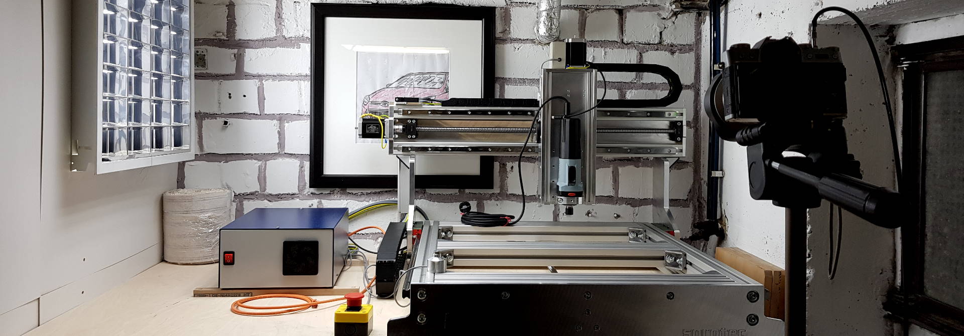
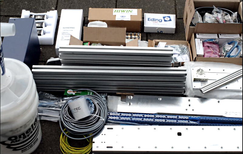
Brand: Sorotec, Product: Basicline 0607
My portal milling machine arrived as an all-inclusive assembly kit in a huge package on a small pallet. After inspecting its contents, I was pleased to find out that all major parts were packed so that I could start the build immediately.
Machine facts
- Fully built, size is roughly 1m x 1m x 0.8m
- Work area: ~ 630mm x 730mm x 135mm
- Weight without spindle, mechatronics, and accessories: 52kg (source: manufacturer)
- ball screws and linear guides on all axes
- Steppers: 3Nm / 4.2A @48V
- Speed & Acceleration config: 200mm/s, 400mm/s²
Assembly
The portal milling machine’s mechatronics assembly took ~16h including stepper motor wiring, terminals, connectors, but excluding the switch box I wrote about here which I spent another 8h on.
The following sections each describe a construction stage, and also mention the things I struggled with.
1. Preparing the ball screw bearings
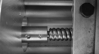
A ball screw (youtube link) is a mechanical actor that converts rotary into linear motion. Instead of direct contact to a nut (like a normal screw), the nut houses a system of revolving balls that reduce friction between nut and screw to a minimum. On the CNC, they are used to move the portal with help of a stepper motor.
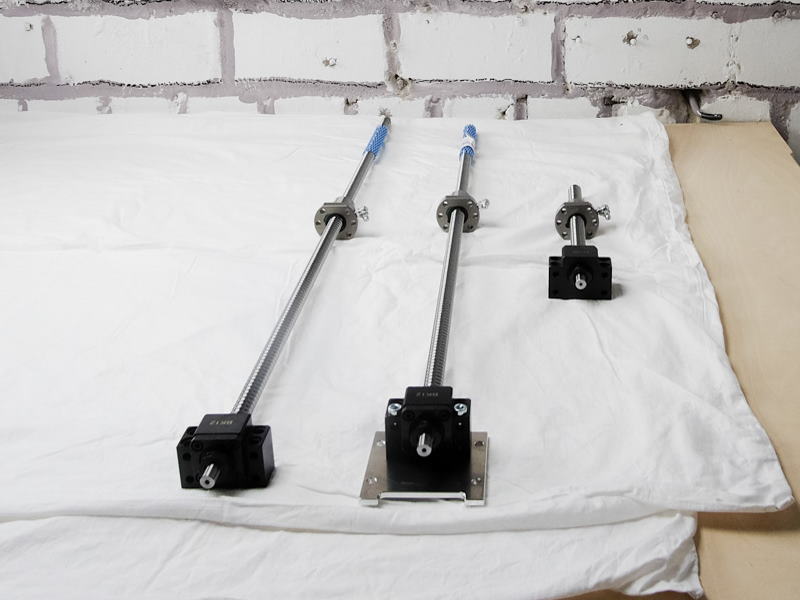
The ball screws need two bearings, a fixed (stepper motor side - black block on the images), and a loose one on the opposite side that just holds the screw in place. Mounting the loose-side ball bearing into its fitting proved to be more difficult to me than I’d have imagined. Im not experienced with metalworks at all, so I had a hard time hammering the bearing in as the fitting was so tight. I accidentally shaved off a bit of the aluminium fitting and the result was terrible.
Fitting of ball bearing gone wrong
Luckily I had a 20mm ratchet nut that fits the outer ring of the ball bearing. After heating up the fitting a bit, I was able to use the nut, carefully hammering the bearing into the fitting with better results.
Fitting of ball bearing after reinstall
Let’s hope the bearing didn’t get polluted too much with aluminium chips.
2. Machine frame
The frame is made of “standard” aluminium profiles connected with brackets. Additional stiffening is provided by massive aluminium plates on front and rear of the frame. Linear guides are mounted to the sides of the frame which later keep the portal in place, allowing movement in X-direction of travel.
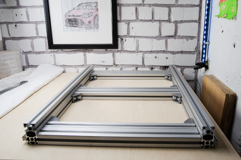
It took me quite a long time to align the frame properly so that every angle would measure 90° and I’d still have some “air” at the right hand side for later arrangement as the gantry would dictate the exact frame width. Problem was that when tightening the screws from one side to the other, somehow the frame would always go out of square and I would have to loosen the screws a bit, then tighten up again, only to see that nothing much had improved.
After a couple of hours of cursing under my breath, I tried to tighten all screws just to 3Nm first, then to 6Nm, 9, etc. This worked very well so finally I reached the targeted 25Nm and was still happy with all the square angles 😅
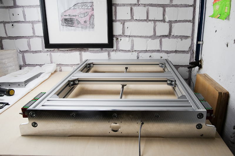
Mounting front and rear plates, the ball screw for the X axis, and the reference switch then proved to be quick and simple in comparison. The image above shows the fully mounted X-axis. Linear bearings that will later carry the portal are already mounted on linear guides. Here’s how the trollies look like on the inside:
Linear bearing with revolving ball system
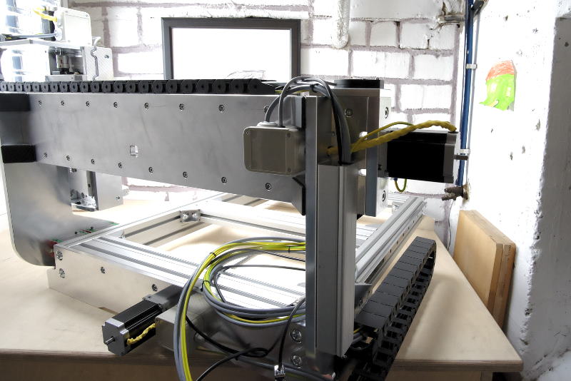
3. Gantry
For this machine’s design, the portal moves in X-direction and provides a flange to the Z-axis that itself can be moved on the Y-axis via a stepper motor on the portal’s left hand side.
First, the portal cheeks are mounted on the linear bearings of the X-axis. Locator pins that the manufacurer designed were a great help to make sure that they are positioned correctly. Then, linear guides for the Y-axis are attached to the crossbeam of the gantry which is then finally hung into the portal cheeks and secured with cast brackets. To keep the crossbar as close as possible to the cheeks before fastening, I used screw clamps.
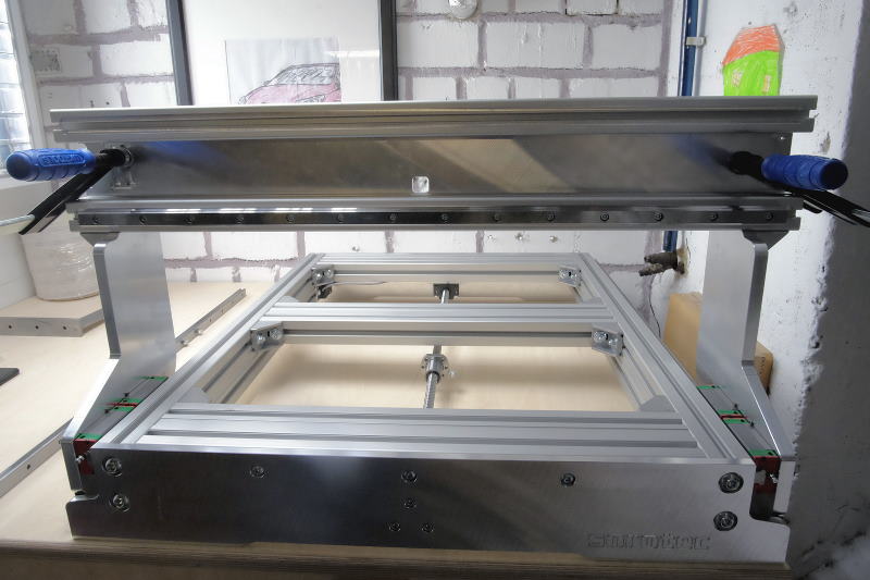
This machine works with a single stepper motor for the X-axis, not with two independent ones on each portal cheak that can be seen on other designs. To make the X-axis ball screw move the portal, a girder is mounted underneath the portal cheeks that connects to the ball screw’s nut. It’s easy to spot in the video below. As the assembly was a bit heavy already and I had to access the underside of the frame, I used a wooden stand to carry one side of the frame while working underneath. This way I could avoid turning the whole machine upside-down.
Easy portal moving by hand - without ball screw attached
After loosening some of the frame’s fasteners to readjust the air-gap with mounted portal, I made sure that the portal could move without difficulty. Then I tightened all relevant fasteners for portal and frame again, using the 3Nm-increment-technique I introduced before to avoid losing square.
Next step was to mount Y-axis ball screws, linear bearings, and flange plate to the portal which luckily was easy enough to do.
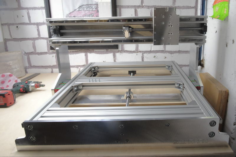
Finally, the Y-axis reference switch could be added along with the motor socket.
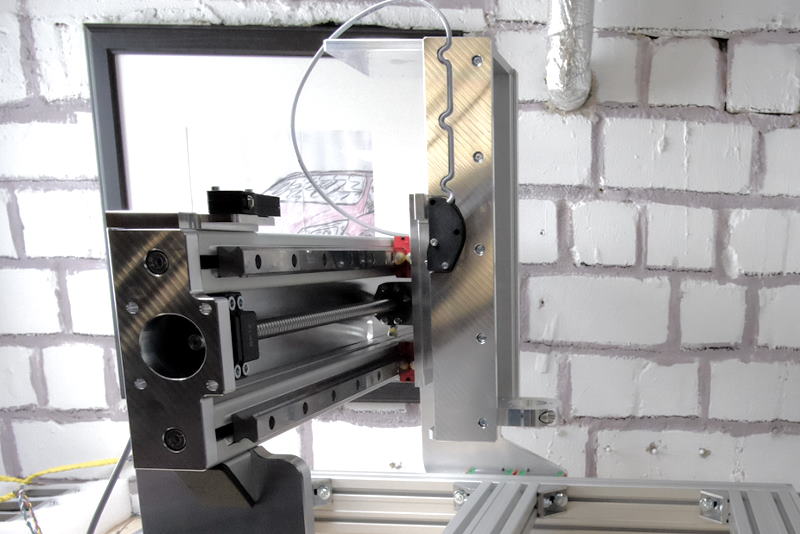
4. Z-Axis
As the Z-axis is a component of its own, I assembled it aside the rest of the machine. Locators would simplify finding correct positions for the bearings, and a single linear guide would keep the Z-axis in place.
I’m pretty sure that this is fine for woodworks, but I don’t know if the stiffness provided by this Z-axis design is enough to routinely work with more challenging materials like Aluminium - for that, maybe a heavier alternative with two linear guides on the Z-axis should be used. Nevermind, I wanted a machine for woodworks and plastics - you get what you pay for.
It’s always nice to see when things really fall into place 🤗 - Look at how snugly the individual parts of this assembly kit fit together!
I like the sound of nicely matching parts!
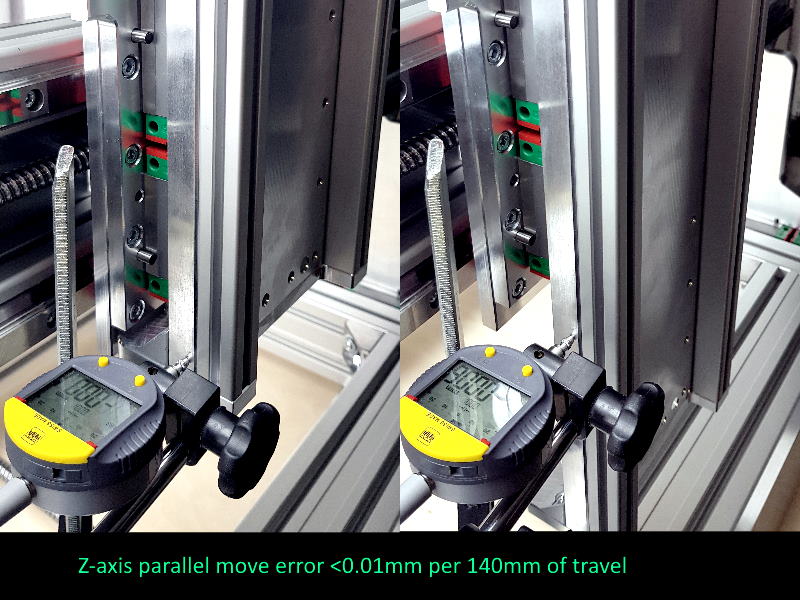
When component assembly was complete, I could mount the Z-axis to the gantry. Then I aligned the Z-axis with help of a dial gauge. What I observed: Even if I had invested much more time in further improving positioning errors, it is enough to push the Z-axis at the bottom end with my hand to increase deviations to above 0.01mm easily. Unless you have a very heavy (annealed steal) machine, don’t expect wonders.
Assembling the stiffening cheeks to the Z-axis (image below) was more tricky than I anticipated. The hammer nuts were so small and the fasteners so short that there was not much room left for wiggling things in place - I had to align again and again to properly position them for sliding the reinforcement cheeks onto the assembly. When this was complete, it was an easy task to mount the Z-axis reference switch.
5. Mechatronics
It’s time to mount the stepper motors I prepared earlier. I lubricated the claw couplings between motor and ball screw with petrolatum and fully pushed it on the screw’s shaft before adding the motor. On the Y-axis, fastening the setscrew was fiddly because the hex key has very little room to act on the motor side. If I had to build this machine another time, I’d do it like this to eliminate the issue:
- Take the clutch apart
- Fasten one clutch half to the ball screw
- Add the other clutch half to the motor shaft, don’t tighten yet
- Put the motor into its mount, only tighten so much you can still move it by hand
- Push the motor’s clutch half into the screw’s
- Take the motor off and fully tighten its clutch
- Now mount the motor
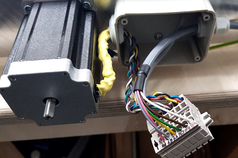
As the motor wires are not very long, there is a small junction box located closely to each motor where both reference switch and motor power wires are connected to drag chain compatible control lines. Every stepper motor also gets a dedicated earth wire leading to the switchbox.
Once this was done for all three axes, I mounted the drag chains. Here, it’s a good idea to thoroughly select the mounting direction because the chains can be opened for maintenance in one direction only. Example: if you need to add or exchange cables later on, it’s frustrating to see that there’s no way of getting the screwdriver in place to unlock the chain links.
Also, please leave the control lines longer than needed and shorten them as a last step before soldering the connectors. For example, the required length of Z-axis wiring may come close to 5m when the switchbox cannot be placed immediately next to the machine.
6. Lubrication
Finally, I followed the (well-made) maintenance manual to get the machine properly lubricated.
Did I mention that I’m not a metalworks guy? Working with the grease gun proved to be pretty frustrating to me. At first, I didn’t manage to get anything out at all and finally, it wouldn’t stop. Now I’ve got a very-well greased working table but a dry machine.
And when is it enough grease? Are two shots into the grease nipple sufficient? I cannot even check whether anything actually entered the linear / ball screw bearings (they have a non-return valve), but the nipples are completely slurred from the outside.
Well, let’s assume everything is fine 😜
7. Missing / bonus parts
As written above, all vital parts of the machine were packed Ok. But some small parts were missing for my machine configuration:
- 18x 18mm M5 hex fasteners (linear guides y-axis)
- 6x 0.75mm cable shoes to get the earth wires mounted
- 4x 22mm M4 hex fasteners (stepper mount)
But I also had some bonus parts
- 1m drag chain extra
- 4 M5 washers
- 9 M4x10 countersunk hex fasteners
I’d recommend to add 100 zipties to the assembly kit so all wires can be kept nice and neat. Cable sleeves would be better still but likely come at higher cost.
8. Critics
I like the construction manual (Version 2.1.5) very much. It contains a parts overview and each step is explained in high detail. Also the build process is well thought-through and I as a non-professional mechanic didn’t have bigger troubles to correctly assemble the machine.
The machined parts have a high quality and are free of ridges or sharp corners. All necessary threads had been cut in advance - even the ones for the optional mechatronics kit - so that I didn’t have to buy tools or gain knowledge about how and where to mount them.
What I didn’t like is that some fasteners were missing holding up the completion for a weekend, and that the expected fastener count wasn’t printed in the manual so I only realized there are parts missing when it was already too late. I understand that this machine can be ordered in different sizes and configurations so it might be too much to expect a construction manual for each and every combination.
Some of the bigger aluminium parts arrived with scratches as the pallet somehow must have broken and torn through the packaging during transport. To me it shows that either the logistics company or the manufacturer didn’t pack the machine 100% safe or maybe underestimated its weight.
A last point about these grease nipples (still no metalworks guy): The one for the X-axis cannot be turned anymore once the ball screw’s nut has been mounted to the lower gantry beam due to missing clearance. This is unfortunate when lubrication suddenly has to be done at a different angle than anticipated. Also, I’m pretty sure the lower grease nipple of the Z-axis points into the wrong direction in the manual.
I tried my best to find things to gripe about but came up with only so much as nitpicking. None of my critics limit the functionality of the machine and neither cost a considerable amount of time or money to fix. So far it looks like I bought a sturdy device that will help me do my prototyping woodworks more precisely and much more quickly than ever before.
This is Zerspanobert!
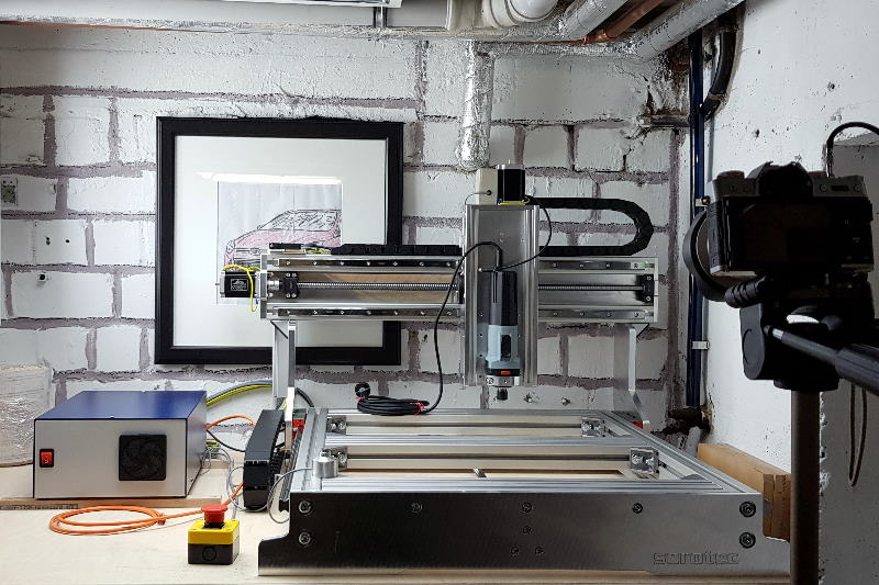
9. Let’s put the machine into operation!
You want more? Machine setup for first use