CNC Tuning #1
This is the first part of my series on optimising production time on CNC milling machines. It focuses on the use of CAD and CAM tools to generate more efficient G-code.
There are various measures to reduce production time with a CNC machine. Firstly, however, it should be analysed why this is desired and what possible disadvantages result from it.
Why at all?
From a commercial point of view, shorter production times ensure a higher throughput of parts and thus enable a higher turnover in a given period of time. In addition, the investment in the machine is amortised more quickly.
As a hobbyist, shorter production times are particularly interesting if the aim is to produce very complex geometries or when performing real 3D-milling. Here, machine times can easily amount to several hours per part and the potential savings are therefore particularly large.
For me, as in teaching, the scientific idea takes centre stage: I want to find out where the limit of the machine lies. I want to know why it is there. I will try to operate it stably within its limits. Still, wear and tear must be kept under control.
However, in order to know this limit precisely, it must first be crossed. How else would I know where it is?
What are the possible disadvantages?
Certain components of an “overclocked” machine could wear out faster than usual. These include power supply units and motor output stages, for example, which have to cope with higher transient currents. Bearings and guides are subjected to greater stress due to higher accelerations. Rotating spindles and machine frames have to absorb the resulting stronger and more rapidly changing forces and vibrations and may show signs of fatigue or loosening connections earlier.
In extreme cases, the machine can even be damaged when the limits are reached: There is a high probability that step losses1 will occur beyond the limit. This is not a problem in test operation. However, the assumed position then no longer matches the actual position and there is a risk of a “crash” - if care is not taken. Here is a pretty good Youtube video by gammaflow on the subject of avoiding step losses.
If the milling paths are changed in CAD or CAM in favour of shorter production times, this can also have negative effects on cut, edge and surface quality.
A compromise must also be made when optimising the path interpreter of the control software: Higher production speed is bought with lower accuracy and/or higher machine wear.
Which measures are not discussed?
I will not consider here the optimisation of the feed rate F and speed S of the selected cutter during machining. These parameters depend on the material to be machined, the endmill geometry, the capabilities of the machine and the courage of the operator, so I cannot suggest any generally applicable tunings.
I must also exclude another major influencing factor here: The machining strategy of the CAM program in relation to rapid traverse. My CAM program does not allow me to intervene very deeply, so I always have to work manually in the G-code to optimise the last few percent of production time, which is correspondingly error-prone.
Tuning in three steps
In my optimisation, I proceeded in three steps, which can be implemented independently of each other. Each step brought me clearly noticeable improvements. This article focuses on engraving operation for several reasons:
- Engraving usually allows for greater tolerances than other modes of operation. This allows greater rounding, which leads to lower accelerations, enabling higher feed rates on average
- The milling forces to be expected are lower: No cutting all the way through, hardly any energy required for chip displacement, smaller chip volume than with end mills
- This allows the machine to be operated closer to its mechanical and electrical limits
- More optimisation potential due to larger G-code files on average
Step 1: Better G-code
This section follows the credo Garbage in, garbage out. In other words: If my G-code is already bad, the machine can never achieve optimum production times. So what characterises “bad” G-code in terms of production time?
- Excessively complex and long, possibly file sizes in the megabyte range
- Extremely many interpolation points and a lot of short line segments
- A bunch of “empty runs” in rapid traverse on XY with the Z-axis raised
- Many retractions of the Z-axis to safety height
- Frequent machine waiting times (spindle run-up, coolant pump, controller buffer full)
- Excessive superfinishing even with B surfaces
But how should I simplify my G-code?
Short question, long answer: It starts in CAD and may not end in CAM.
Example CAD
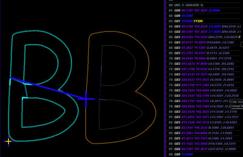
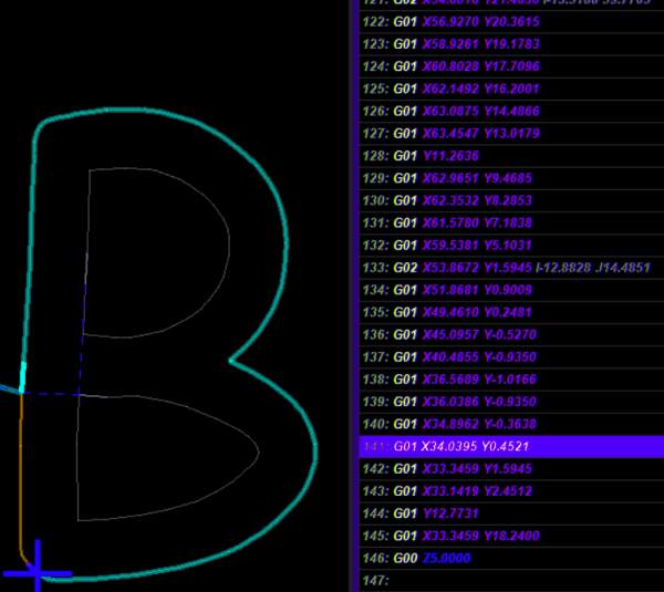 Let’s assume we want to mill some letters. Our CAD program has a bunch of great fonts for this. We now create a DXF file for the CAM. In the CAM, when we zoom in, we suddenly see that all the letters consist of very short line segments instead of circle segments or splines. The result: The CAM will generate
 G01 movements, i.e. “linear moves” or a sequence of lines.
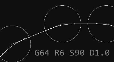
The connected paths require the machine to change direction very often. Consequently, it must always decelerate before the connection point and then accelerate again. The machine cannot therefore travel at a constant speed, as this would require infinite acceleration at the bend point.
There are solutions to this problem, which are ideally used together:
- Set the CAD programme to create splines or curves instead of line segments whenever possible
- Simplify the drawing by reducing the number of support points
- Increased use of radii and splines at edges, avoidance of angles
In my case, the first option was not available, so I now use a different programme for engraving fonts than for my usual drawings. As a result, I can now express lettering in line and arc segments. The milling time required for this is halved and at the same time the G-code manages with fewer lines. In addition, the cuts become rounder and adheres even more closely to the initially selected font.
Gimp and Inkscape provide good examples of simplifying paths by reducing vertices - I have already shown this for Inkscape in my article on image-to-path conversion. With just a few clicks, you can obtain drawing data at the expense of accuracy, some of which can be produced much faster.
As an end mill cannot produce a pocket with r=0 in the corners anyway, I have got into the habit of rounding off all corners and edges in CAD. Not only do parts produced in this way fit better in the hand, they are also quicker to produce - the time savings add up, especially on slow and sluggish machines.
Example CAM
In CAM, I can save a little time by increasing the use of approach points and ramps. I usually place them on the shortest line segment and thus save one braking/acceleration process. With the plunge type, the advantage of “ramp” over “helix” is that all paths of the cutter are effective paths and I can drive through without additional axis accelerations. Depending on the ramp gradient, however, the milling path is longer as overlaps occur.
The clever selection of clearing infeeds and strategies for pockets to suit the material, milling cutter and desired surface finish has a much greater effect on the production time. In many cases, trochoidal milling2 produces longer files and takes more time on the machine than the classic “lawnmower”, which simply files the pocket. For the clearing infeed, I like to choose large values above ‘60%’ for materials such as wood and acrylic glass - unless the bottom of the pocket has to meet particularly high quality standards.
In my opinion, it is quickest for engravings not to use a second cutter for pocket clearing. Instead, use an engraving bit with a flattened tip - similar to those for my tests with Dibond. This takes longer to clear, but I can compensate for this by increasing the engrave depth and a fairly wide flattening of 1.5mm. I use a clearing infeed in XY of 1mm with such a milling cutter. What remains is the time advantage due to fewer tool changes.
But how can I reduce the empty runs?
At last a few crisp, short answers:
- Lower retraction height in
Z(I use5mmbut2mmwould probably also work for me) - Optimise the milling strategy in the CAM to “minimum paths”
- For nesting: Make sure that the geometry is not produced line by line, but part by part.
- If in doubt, optimise the G-code by hand. Worthwhile if the CAM program cannot work well enough and many identical parts have to be produced
And where is the problem with retractions of the Z-axis?
- Retractions occur very frequently, especially in engraving operations
- the loss of time adds up
- When re-engaging, the material is usually not moved at rapid traverse but at the speed intended for the milling cutter with
G01.
Good planning of the milling sequence in the CAM can bring an improvement here. As many sections as possible should be connected and produced in one go without retractions. In CAM, rapid traverse should be used for retraction and re-entry in ‘Z’.
How do I reduce waiting times?
Cooling lubricant switching processes, spindle speed changes or tool changes are associated with waiting times that can usually be easily reduced:
- Allow minimal quantity lubrication to flow during the whole job sequence
- using as few tools as possible at the same speed for a product
- Use stops to simplify machine loading and avoid having to set zero points again and again
- If the machine is operated with completely different parameters for engraving and milling operation, it is advisable to install the control software twice with the appropriate parameter sets in each case. This eliminates the need to always change the configuration.
Continue in Part 2: Turning up kinematic parameters.
-
Step losses occur when the axis of a stepper motor no longer rotates synchronously with the step sequence given by the controller, but instead travels fewer or more steps than dictated. Step loss is almost always caused by inadequate system design (e.g. insufficient or unstable supply voltage, output stages that are too weak or not adapted to the motor) or overloading of the stepper motor. Rarely, however, step losses can be symptoms of defects such as bearing seizure, winding short circuit or blown buffer capacitors. ↩
-
Trochoidal milling is not a bad practice. It has other strengths, but is rarely useful in engraving. ↩