CNC Tuning #3
This is the final part of my series on optimizing manufacturing time on CNC milling machines. It focuses on the path interpreter of the CNC control software.
The control software path interpreter is responsible for reading the instructions from G-Code and translating them into machine movements. For example, if G01 X100 Y200 Z-2.0 F2000 S18000 is to be executed, the interpreter must take into account the kinematic parameters of the machine: which ramp is used to accelerate to the target feed, whether the desired feed is even permissible, and from which point braking must be carried out again in order to reach the target point exactly. The data obtained in this way is finally translated into a step sequence for the three stepper motors, loaded into a buffer memory and finally output to the motor amplifier stages in real time.
Step 3: Optimizing the path interpreter
 Many control software providers have programmed integrated milling path filters, which can be configured using the
 G64 command or via the menu. I’ll link a few examples from different manufacturers here, where you can read about specific details:
The trick now is to find a configuration that suits both milling job and machine kinematics. It’s always about a compromise between production speed and path tolerance. If you want to run at high feed rate, sharp edges are actually rounded, connected line segments are approached within a tolerance band or paths are simplified so that path points outside the acceleration that can be achieved by the machine are not just a pass-by.
Basics: What is Look Ahead Feed?
This means that the path interpreter of the control software is already looking at the next operation(s) while executing the current milling operation - the algorithm checks how it must brake and accelerate again ahead of time and how to best interconnect, interleave or filter path segments. I explain the physics behind it in the CNC setup article.
This can save a lot of time, the milling process becomes more fluid and the machine experiences less stress. In addition to avoiding acceleration and braking processes, parameter G64 can be used to set whether and how milling path filters are allowed to change the planned trajectory in order to further optimize for higher path speeds.
Ideal for engraving operations
Such options can be used excellently in engraving operations: higher tolerances are usually OK here, and slightly rounded edges are often acceptable. With 3D engravings, milling through the many paths takes a long time, and a lot of time can be saved here.
Since I use EdingCNC, I can only give tips for parameters of this control software. Now let’s go into detail about the settings!
Milling path tolerance G64 P*
 This parameter specifies the general tolerance of path accuracy to the control software.
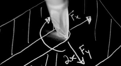
I have set my machine so that it allows deviations from the specified milling path of up to LAF blending tolerance = 0.3mm in engraving mode. Alternatively, the configuration can be done using command G64 P0.3. In the picture I have sketched how such a setting can work in practice: The milling path (white) consists of G01 line segments. The tolerance is marked with the help of circles. The path interpreter of the control software can now independently define circle segments so that the highest possible path speed is achieved within the tolerance.
The path determined in this way (turquoise) resembles a spline curve. It should be noted that all lines can be affected by this setting - even those that have strict tolerance requirements. If this is not desired, a smaller value should be used here.
Path rounding G64 R*
If two line segments meet at an angle of up to LAF full speed blending angle threshold = 12°, the machine will try to follow the angle exactly without braking. For larger angles, travel is carried out at reduced speed with a tolerance defined by G64 P*. This configuration is programmed with G64 R12.
The values here must be set with great caution because they lead to acceleration peaks on the machine. Large values can cause step losses and increased wear on the CNC milling machine. To achieve this, the path speed and accuracy are maintained optimally.
Path rounding at reduced feed G64 S* D*
 This configuration gives the control software the ability to round edges up to the set tolerance value:
 LAF reduced speed path smoothing delta = 0.001mm. In combination with the rounding, the angle up to which this rounding should be carried out must be set: LAF reduced speed path smoothing angle threshold = 0°.
This function is best programmed in combination with path rounding at full feed like so: G64 R* S* D*. The advantage here is that line segments are followed very precisely as shown in the picture, and at the same time the edges are rounded off in a finely adjustable way. Up to the angle defined via R, the path is followed exactly, even at full feed.
If very large angles are set at S, there will be greater rounding corresponding to D. However, if the angle specified in the milling program exceeds the configured value, the algorithm falls back to the values stored in P or to the exact path following mode.
Path simplification G64 Q*
 If the G-code file contains numerous, very short line segments (as is often the case when creating paths from image files), this function can help by simplifying the milling paths. The number behind the parameter indicates the tolerance up to which line segments are merged into a line.
This setting relieves the load on the machine’s buffer memory and at the same time increases the average path feed rate. I think this setting is particularly interesting for engraving operations when working with “noisy” data and there was no option in CAD to reduce the number of paths.
Acceleration filter G64 F*
Using these parameters, the acceleration peaks that may be generated by Look Ahead Feed can be mitigated. The minimum value to be set is determined by the quotient of the selected feed for the operation and the maximum speed of the machine.
Example: Fmin = Foperate / Fg00, with Fg00 = 12000mm/min and Foperate = 5000mmm/min, Fmin = 0.42
So at a feed rate of 5000mm/min the maximum possible acceleration of the machine is called up and the curve radii are set so that they are ran at a constant path speed. All values greater than or equal to Fmin = 1 are inherently safe, regardless of the selected feed rate.
 This parameter was introduced for better processing of elastic materials such as rubber or cork, where a constant feed speed is critical and path stability is of secondary importance. The parameter is used in combination with
 G64 R*. The following programming for the example above would call up the full capacity of the machine: G64 R120 F0.42, whereby F5000 is used, F12000 is the maximum feed of the machine and acute angles up to 120° are taken without braking at all.
If I apply these values to my machine, the image shown opposite is created. A rectangle with an edge length of 25 x 100mm should be made here. The target trajectory is again shown in white. The turquoise curve shows the curve with a constant path speed that was driven by programming the acceleration filter. The lower the feed in relation to the maximum feed and the higher the acceleration of the machine is set, the smaller the necessary radius becomes.
However, in my experience, this parameter is not used for engraving and milling solid materials.
My configuration for the Hobbyline 4530
I played around with the various LAF settings at the cost of a lot of blanks to learn and improve parameter settings. I achieved the shortest production times by previously optimizing the kinematic parameters with the following configuration:
G64 Q0.3 R12 D0.3 S120
With that I tell the machine the following:
“Use the look-ahead feed algorithm and try to merge short line segments less than
0.3mmin length. Try not to reduce feed rate when two line segments are at an angle of less than12°. At larger angles up to120°, rounding can be done with up tor=0.3mmtolerance. For even larger angles, the specified path must be followed. If necessary, brake to a standstill.
Conclusion
 Since the parameter optimization for engraving operation took me quite far away from the parameter set for normal milling operation, I simply installed my control program a second time.
There I was then able to specify the speed, axis acceleration and path parameterization separately. Now I have the best of both worlds on one machine:
A very precise, smooth milling operation with the following parameters:
Fmax XY 12000mm/minFmax Z 4800mm/minAmax X 1000mm/s²Amax Y 1000mm/s²Amax Z 1000mm/s²G64 P0.1 R6
And via the other link an extremely fast engraving operation:
Fmax XY 12000mm/minFmax Z 4800mm/minAmax X 4000mm/s²Amax Y 3200mm/s²Amax Z 1600mm/s²G64 Q0.3 R12 D0.3 S120
And where is the proof?
The embedded video shows the same engraving project with four different levels of optimization:
- top left: stock configuration of the machine, standard milling paths from CAD/CAM
- top right: Speed and acceleration increased to “milling mode”
- bottom left: Look Ahead feed switched on
G64 P0.3, milling paths optimized in CAM - bottom right: Optimized for “engraving mode” as described above, CAM flyover reduced to
2mmand empty runs minimized