Hardware Test
Ein neuer AntriebPermalink
Kürzlich habe ich Zerspanobert ein Spindel-Upgrade gegönnt. Ich bin jetzt auf eine Drehstrom-Asynchronmaschine umgestiegen, welche mit einem 24V-Lüfter fremdgekühlt wird. Für den Betrieb im benötigten Drehzahlbereich musste ich in einen Frequenzumrichter investieren, der in meinem Falle wie beim vorigen Fräsmotor auch über ein analoges 0-10V Signal gesteuert wird. Aus Sicht der CNC ist die neue Spindel bis auf eine Ausnahme identisch mit der alten: Der Frequenzumrichter kann nun ein “Not-Aus” Signal erzeugen und an die Steuerung melden, z.B. wenn die Drehzahl ungeplant abfällt, zu lange ein Überlastzustand auftritt etc.
Wie man sich vorstellen kann ist das neue Subsystem rund um die Spindel deutlich komplizierter als das alte.
Warum extra Tests?Permalink
Mit höherer Systemkomplexität erhöht sich auch das Risiko für Fehlfunktionen. Es sind eine Menge mehr elektrischer, elektronischer und mechanischer Bauteile verbaut als bei meinem Fräsmotor, die selbst Defekte aufweisen oder bei falscher Verdrahtung selbst in Rauch aufgehen können. Da ich als Systemdesigner selbst nur ein Mensch bin der Fehler macht, wäre es nicht besonders schlau, das System irgendwie zusammenzustecken und dann direkt auszuprobieren.
Während ich die Verdrahtung erstellte, überlegte ich mir also, wie ich das System effizient testen könne, ohne etwas zu zerstören.
TeststrategiePermalink
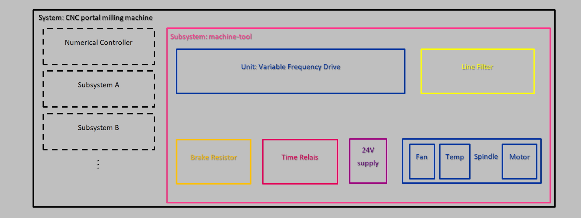
Ich habe die unterschiedlichen Testbereiche von meiner Arbeit in der Softwareindustrie geborgt. Sie passen hier denke ich recht gut hinein:
- Unit: Ein Test, der das Verhalten einer Komponente des Systems isoliert überprüft. Alle externen Einflüsse wurden entweder entfernt oder durch Komponenten ersetzt, auf die im Test selbst problemlos zugegriffen werden kann. Beispiel: Prüfe, ob der Lüfter bei Anlegen seiner Betriebsspannung wie erwartet im richtigen Drehsinn anläuft.
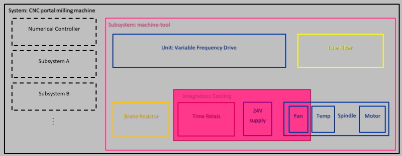
- Integration: Diese Tests prüfen das Zusammenspiel verschiedener Komponenten, welche gemeinsam eine Funktion abbilden. Beispiel: Überprüfe, ob die Luftkühlung der Spindel auch nach Abschalten derselben für eine bestimmte Zeit nachläuft.
- Subsystem: Verifiziert die korrekte Interaktion aller Komponenten eines Subsystems. Beispiel: Die Spindeldrehzahl kann über eine analoge Spannung am Eingang des Frequenzumrichters verändert werden.
- System (End2End): Diese Tests werden aus Kundensicht ausgeführt und durchlaufen das komplette System. Beispiel: Wenn ich den Not-Aus an der CNC betätige, muss der Frequenzumrichter die Spindel umgehend sicher zum Stillstand bringen.
Teste frühPermalink
Aus meiner Erfahrung macht es Sinn, die Tests zum frühestmöglichen Zeitpunkt durchzuführen. Nachdem die Spindel geliefert worden war, konnte ich auf diese Weise sofort nachvollziehen, ob alle Lager leichtgängig sind, ob der Lüfter funktioniert und ob der elektrische Widerstand der Statorwicklungen im erwarteten Bereich liegt. Alle diese Tests waren durchführbar noch bevor ich mit dem Bau des Schaltschranks überhaupt begonnen hatte.
Unit test: Lüfter
Die schnell und einfach durchführbaren Unit Tests können einen Haufen Zeit sparen, denn diese Fehlerquellen kann man später bei der Inbetriebnahme direkt ausschließen. Und findet man doch etwas so früh, kann man sich direkt um Ersatz kümmern und hält nicht den Einrichtbetrieb auf.
Teste “von unten nach oben”Permalink
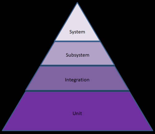 Bei den vier Testebenen versuche ich, so viel wie möglich mit einfachen und schnellen Unit Tests abzudecken. Was hier noch nicht geht, wird jeweils auf der nächsthöheren Ebene abgearbeitet und so weiter. Am Ende möchte ich nur ein paar Wenige Tests aus Kundensicht durchführen, da diese meist einen größeren Aufwand für Vor- und Nachbereitung benötigen und außerdem zumeist nicht genau in der Lage sind, den Fehler zu lokalisieren.
Dies deckt sich mit dem Konzept der Testpyramide, welche in der Softwareentwicklung des Öfteren herangezogen wird.
TestplanPermalink
Für meine privaten Hobbyprojekte schreibe ich üblicherweise keinen Testplan. Meine Systeme sind meist deutlich einfacher als dieses. Außerdem benötigen nur die wenigsten potentiell gefährliche Niederspannung wie in diesem Fall.
Um das System besser zu visualisieren habe ich mal einen groben Schaltplan mit allen Komponenten sowie relevanten Ein- und Ausgängen gezeichnet.
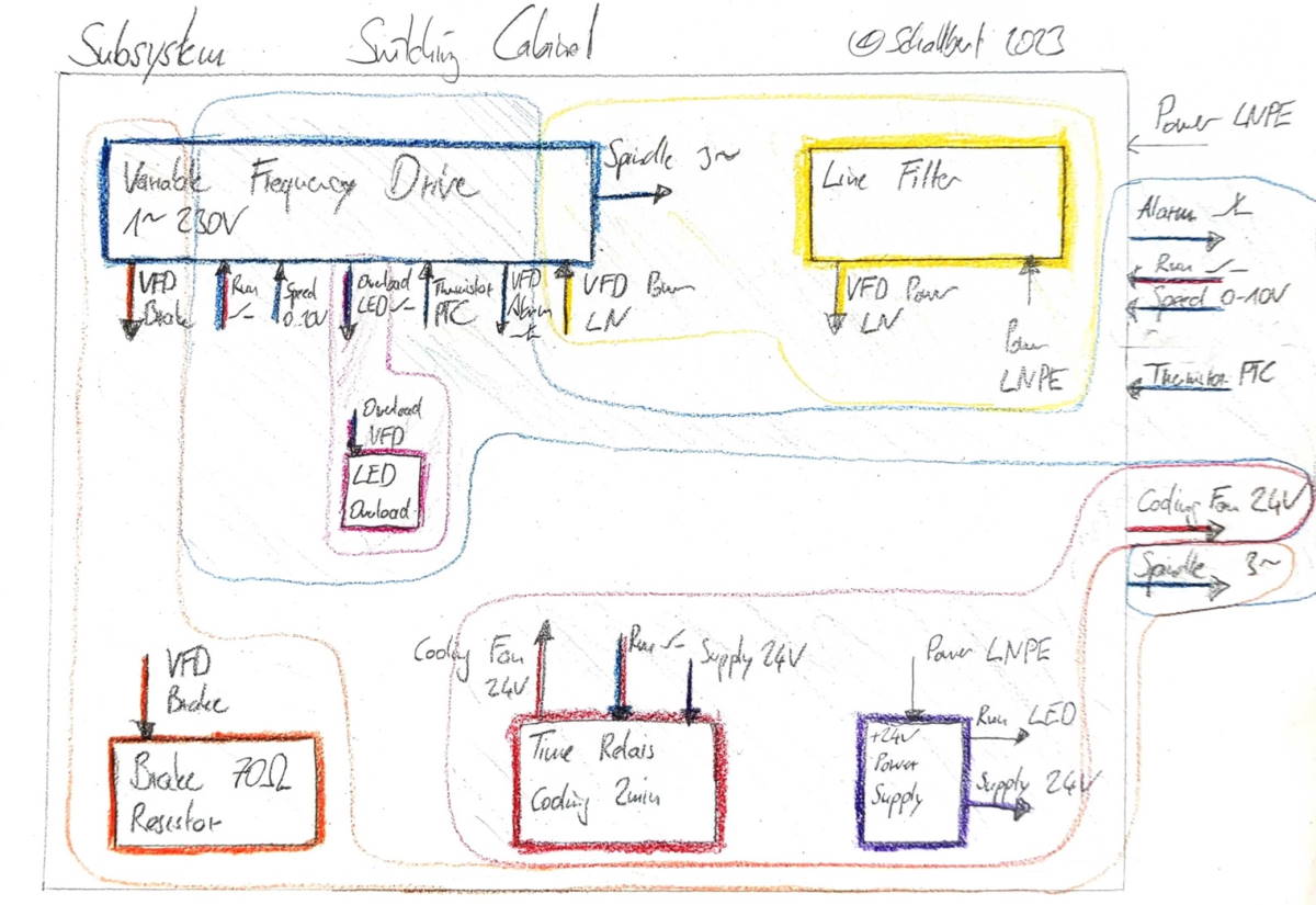
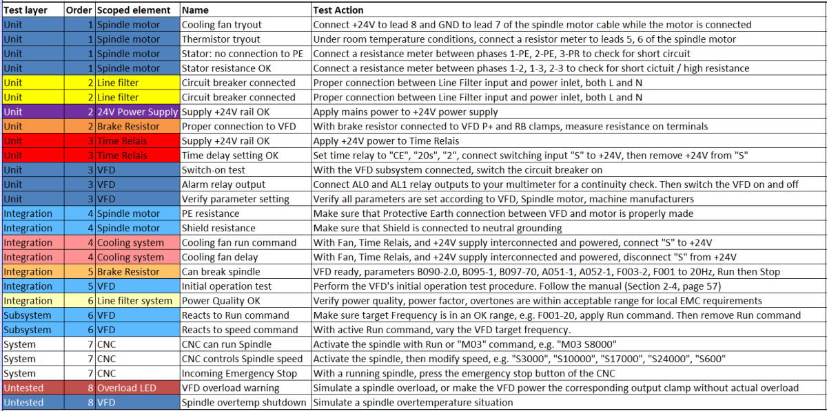
Von diesem Bild habe ich einen Testplan abgeleitet. Hierbei habe ich versucht, die Interaktionen jeder Komponente mit jeder anderen abzudecken und wenn möglich versucht, dem Komponententest den Vorrang zu geben.
Unit test: Stromversorgung +24V OK
Hier überprüfe ich die Versorgungsspannung für den 24V-Lüfter
Unit test: Abfallverzögerung
Mit diesem Test stelle ich sicher, dass die Konfiguration der Anzugs- und Abfallverzögerung wie gewünscht funktioniert. Für den Test habe ich kürzere Zeiten gewählt als später im produktiven Betrieb.
Integrationstest: FU Inbetriebnahme
Hier prüfe ich, ob der Frequenzumrichter die Spindel mit der korrekten Drehrichtung und mit unterschiedlichen Drehzahlen betreiben kann.
Ausführung der TestsPermalink
Es gibt natürlich noch viele weitere hardwarebasierte Tests die ich oben nicht erwähnt habe. Dinge wie “ist die Spindel korrekt mit der Z-Achse ausgerichtet?” “Habe ich alle Schrauben mit dem vorgeschriebenen Drehmoment angezogen?” “Sind alle Stecker angeschlossen und verriegelt?”
Bevor ich nach dem Umbau also das erste mal wieder Späne mache, habe ich den Testplan komplett abgearbeitet und tatsächlich ein Problem auf Systemebene entdeckt: Ich habe den Analogausgang zur Vorgabe der Spindeldrehzahl falsch verdrahtet, sodass andere Pins das Signal führten als geplant. Dies führte dazu, dass sich die Spindel trotz Freigabe nicht starten ließ, obwohl die CNC “Spindel läuft” ausgab.
Dank der vorausgehenden Tests am Frequenzumrichter (“Reacts to speed command”) habe ich nur Minuten benötigt um den Fehler zu finden und zu beheben - denn ich wusste, am FU liegt’s nicht.
DokumentePermalink
Falls Sie planen, eine Frequenzumrichtergesteuerte Motorspindel an Ihrer Maschine einzusetzen, können Sie sich meinen Testplan kostenlos herunterladen. In case you plan on adding a VFD-controlled spindle motor to your machine, please find my full test plan below.
VFD-controlled spindle motor test plan
Aber bitte betrachten Sie diesen Plan mehr als Unterstützung denn als vollumfängliche Prüfung und beachten Sie vor allem die üblichen Warnhinweise:
⚠️ Warnung vor gefährlicher Spannung ⚠️
Dieses System sollte nur von Profis konstruiert, zusammengebaut, angepasst, in Betrieb genommen und schließlich fachgerecht geprüft werden. In diesem Falle meine ich mit “Profi” jemanden, der eine abgeschlossene Berufsausbildung zum Elektriker oder Elektroniker, optimalerweise in der Fachrichtung Anlagenbau/Betriebstechnik sowie Erfahrung im Umgang mit Industrieelektronik vorzuweisen hat. Vermeiden Sie insbesondere, unter Spannung stehende Teile zu berühren oder an einer der Komponenten zu arbeiten, bevor der Frequenzumrichter nach dem Abschalten genügend Zeit hatte, seine Pufferkondensatoren zu entladen.


