Hardware Test
A new drive
Recently, I bought a spindle upgrade. I now switched to a 3-phase induction motor with forced air cooling that requires a Variable Frequency Drive so I can set different speeds. The system takes the same analogue 0-10V signal as my previous motor. For the numerical controller it looks the same with one exception: The VFD can now create an emergency stop signal if something goes wrong.
As you can imagine, the new spindle subsystem is by far more complex than the old one. I had to buy, wire, and setup a dedicated electric control box.
So why testing?
With higher complexity comes higher risk of failure. There are more electrical and mechanical parts involved that each can behave incorrectly or even be destroyed if connected improperly. As I am just a human being who makes mistakes, I’d better not jump in at the deep end. So, while wiring everything up, I wondered how such a system should be systematically tested.
Test Strategy
I borrowed the different test scopes from my job in the software industry. I think they fit in quite well:
- Unit: Test that verifies behavior of a component of the system in isolation. All external influences are removed or mocked away. Example: Check if the blower turns if supplied with its nominal voltage.
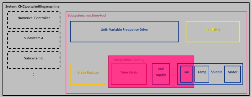
- Integration: These tests integrate different components that provide a common functionality. Example: Verify that spindle cooling works with delayed shutdown.
- Subsystem: Test that verifies the correct interaction of all components within a subsystem. Example: The spindle speed changes when feeding the analogue input of the VFD with different voltages.
- System (End2End): Tests that verify a system from the end-user perspective. Example: When pressing the emergency off switch of the CNC, does the VFD bring the spindle to a halt safely?
Verify early
From my experience, it makes sense to perform tests at the earliest possible point in time. After the spindle was delivered, I was able to check right away whether all bearings were smooth-running, if the fan would turn when voltage was applied, and see whether the motor windings were within expected resistance range, and so on. I could do these unit-level tests even before I started building or wiring the control box.
Unit test: Spindle cooling fan
This might save a lot of troubleshooting when something doesn’t seem to work correctly during comissioning. And if you find something this early, you can directly get in touch with the manufacturer of the affected component to request an exchange while not being blocked on the other end.
Bottom-up testing
 The four levels of testing are my verification strategy here. I try to have many simple and quick early test on unit level, and just a few complex system tests that each involve a multitude of preparation and test steps, being executed just once upon initial startup when the build is complete.
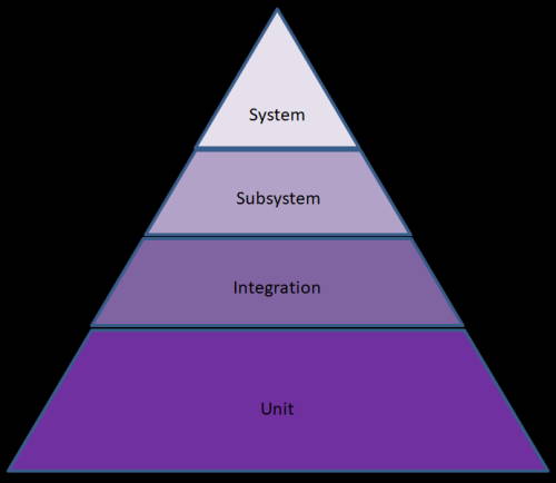
When you look at the concept of the test pyramid that is used a lot in software testing, it may be applicable for hardware tests as well to some extent, maybe with a different number of layers and varying names for the levels of integration.
Test plan
I don’t usually write test plans for hobby projects because the systems I design are rarely as complex as this. Plus, most of them do not require dangerous voltages to operate unlike this one.
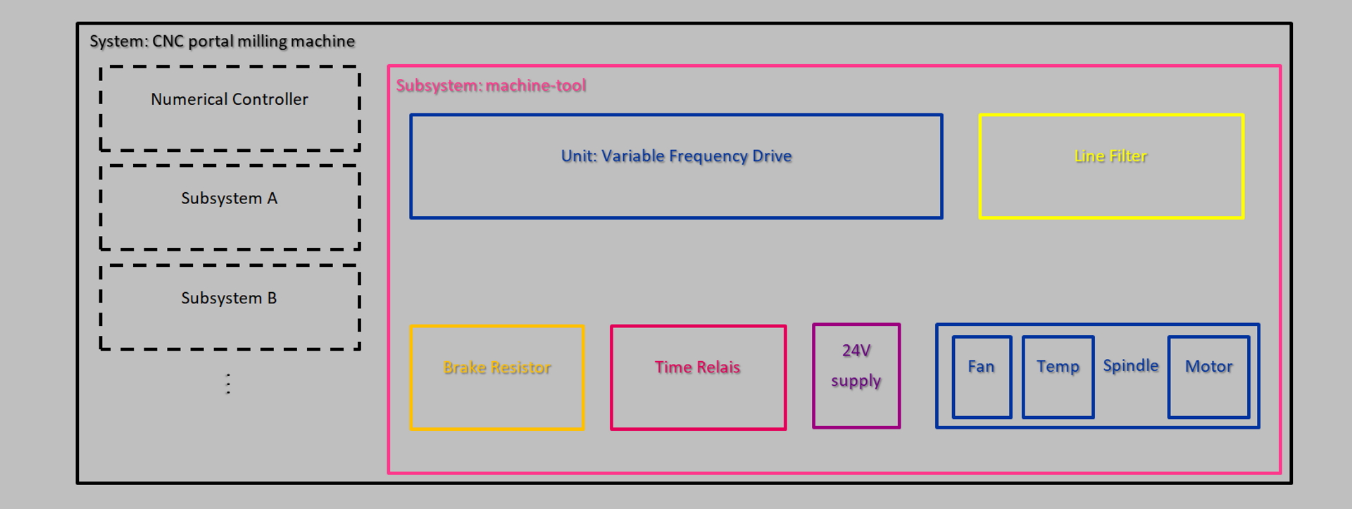
To better visualize the system, I drew a layout of all components with the most important inputs and outputs.
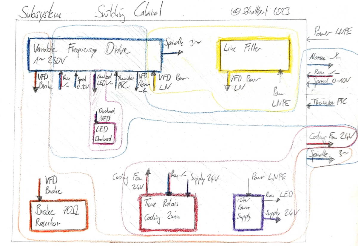
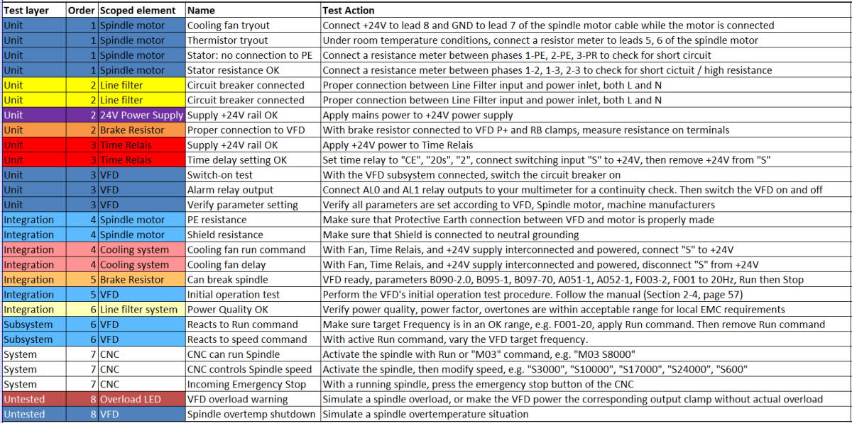
From that image, I derived a test plan. I tried to cover each component’s interactions with each other, ending up in more unit than system test cases.
Unit test: Supply +24V rail OK
Here I checked whether the cooling fan power supply operates correctly.
Unit test: Time delay setting OK
With this test I verify that the cooling fan relay configuration and activation work as expected. For the purpose of this test, I selected shorter delay times than in the later application.
Integration test: VFD initial operation
The variable frequency drive is able to turn the spindle in the correct direction of rotation at different speeds.
Test execution
Of course, there were many more hardware-based tests that I didn’t mention in the above plan. Things like is the spindle correctly aligned to the Z-axis? Have I fastened all clamps with the appopriate torque? Are all connectors inserted and locked?
Before trying to run through material on the CNC I performed all the tests and actually found one issue on the system level: I had a pinning error in the spindle speed analogue output of the numerical controller’s signal harness so that the spindle motor system wouldn’t start despite the run signal being present.
This just took minutes to figure out because I had subsystem-tested the VFD before (Test case: “Reacts to speed command”), knowing that it cannot be the culprit.
Documents
In case you plan on adding a VFD-controlled spindle motor to your machine, please find my full test plan below.
VFD-controlled spindle motor test plan
But please take this plan with a grain of salt and note the usual disclaimer:
⚠️ Risk of electric shock. ⚠️
This kind of system should only be built or worked on by professionals. Especially avoid touching live parts or VFD components before the VFD’s bleeder resistors have had enough time to discharge the intermediate circuit’s bulk capacitors.