Measure Inrush current
Setting up the multimeter / oscilloscope / data logger

For this blog post, I was lucky to borrow a multimeter for energy measurement from GMC Instruments. It features a data logger so I can visualize the collected data.
Metrahit Energy
I’d rate the “Metrahit Engergy” to be more in the ‘pro’ than in the ‘hobbyist’ corner of multimeters, both its wealth of features and its price tag point in that direction. In contrast to lower-range models, it provides modes for instantaneous and average voltage/current, is able to measure power, power quality, and energy consumption of devices. It is also able to show total harmonic distorion of a signal and to read PT100 industry-grade temperature sensors.
This piece of equipment might come in handy for future articles as well.
MetraWin software setup
- Download and install the MetraWin software to transfer and display collected data from the multimeter
- Download and install Driver-Control software. It’s purpose is to provide a communications port between USB and the infrared communication interface adapter provided with the multimeter.
- In MetraWin software, select
METRAHit Starline Series(btw, unclear to me why the series’ name neither appears on the device nor the website)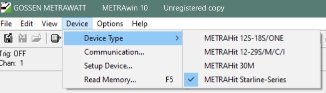
- Connect the infrared adapter. In the device manager (
Windows-key–> typedeviceand selectdevice manager–> scroll down toConnections (COM & LPT), unfold), make sure the IR adapter shows up with aCOMport ID). Select this ID in MetraWin’sDevice --> Communication... --> SEL-COMwindow.
Multimeter setup for inrush current logging
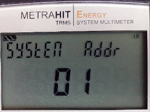 In the Multimeter’s settings, make sure the address is set to any other value than
 00(Setup --> Set --> System --> Addr) because the infrared communication will not detect the device with an invalid value here (I experienced this and needed quite some time to figure out that not the IR adapter detection is faulty but the Multimeter’s settings). Background is that by address, the software supports up to 15 devices simultaneously.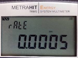 Set the sample time to its lowest value for good impulse tracking: go to
 Measure --> Store --> Rateand select0.0005secwhich means the logger takes measurements with2000Hzsample rate. This is as low as it gets, and these values already compromise the recording channel availability e.g. for energy measurement due to the device’s limited buffering ability.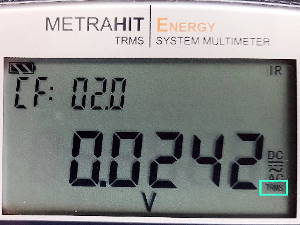 Now select the value you want to measure (for me it is
 DCcurrent inAmpère), hitMAN/AUTOand choose the range manually to a value higher than the peak value you’re expecting. Hint: If you just selectAand the Multimeter showsTRMSorRMSsomewhere, this is likely not what you want because with this option, the device will do some maths to get average values which naturally does not work when we want signal peaks.
For my amplifier’s inrush current, I had to set the range manually to >10A. This is because if the signal peak exceeds the ‘Auto’ range by far, accuracy will be low and the device might even record complete nonsense.
Alternative devices
Oscilloscopes would easily outperform the multimeter in terms of sample rate but as they have completely different design requirements, it’s fair to say that you cannot really compare these two device categories.
Nevermind, you can do the exact same measurement with the cheapest of scopes e.g. connected to a 0.1 Ohm shunt resistor as well, and set it to 1V/div. What for this specific task likely won’t work is a low-cost multimeter with “Data Max Hold” function. For capacitor charging on a DC power supply, the sample rate will be just too low.
Discussion of circuit to measure
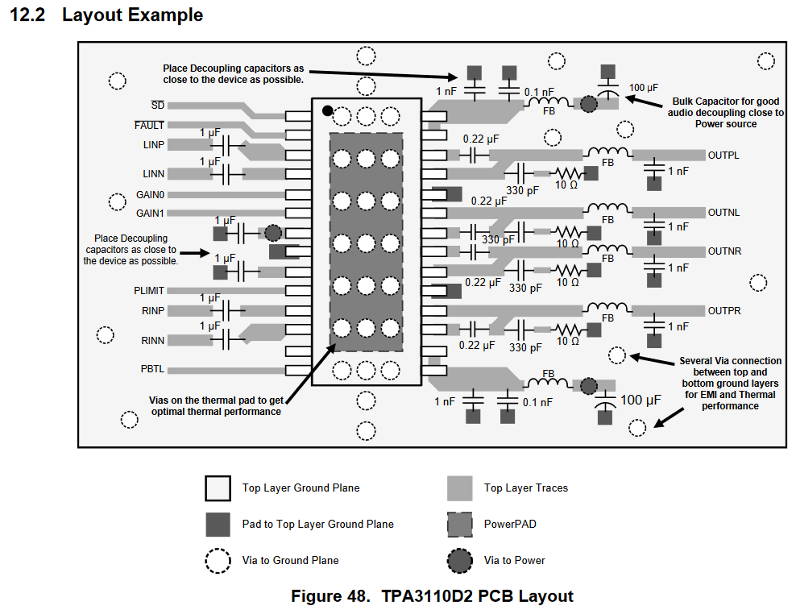
The device under test is a 30W power amplifier board AA-AB32996 by sure electronics based on the Class-D integrated circuit TPA3110.
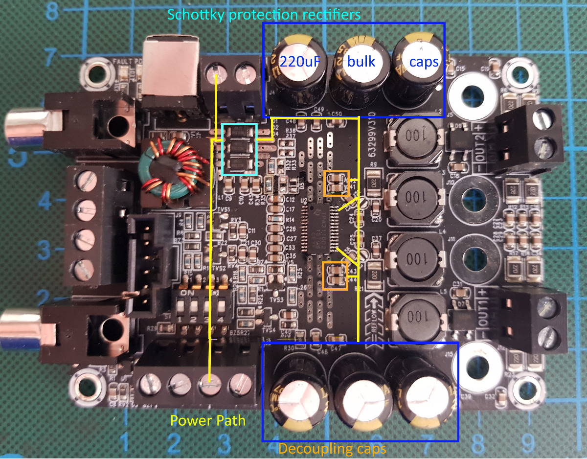
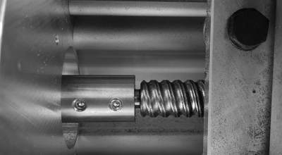
The supply path involves reverse voltage protection schottky diodes (three in parallel), connected to 6 bulk 220uF electrolytic capacitors on the positive supply rails of the amplifier IC. In addition, two different decoupling capacitors close to the IC reduce noise on that rail.
For comparison, the PCB layout example looks similar. You can see that the example features additional FB (ferrite beads) components for current leveling on the input rail and has less bulk capacitance for current surge handling capabilities. Also, the example works with more simple ferrite beads instead of “proper” inductor filters on the speaker output.
Motivation: Failed Prototyping with USB-C PD
For one of my prototypes, I connected the USB-C Power Delivery development board I discussed in this post and had to learn that it would blow up after just a few switching cycles - supposedly due to a high inrush current the power delivery device couldn’t handle.
That’s why I wanted to know how high the inrush current actually is and with which component I could effectively reduce the risk of voltage instability or even component damage when switching the amplifier on.
Actual measurement
I connected the multimeter’s current input to the negative power supply path of the amplifier, its GND connector to the power supply’s GND, +20V of the power supply to the amp’s positive power in, and the Multimeter’s voltage input to the IC’s power supply pins.
Then I selected SET --> Store --> Start --> Store to begin the measurement and connected the positive supply path. As voltage/current stabilized, I ended the measurement by pressing Stop.
Due to the high data rate, I had to transfer the data to my computer manually and couldn’t use the “live” function. To do this, I hit Read Memory --> Get Memory Info --> Move Memory Data to File --> save --> Open Memory Data File --> Display Data from File. Not entirely clear to me why the process has to be that complex - I’d like a shortcut to directly display data from the device - but nevermind, it works pretty well this way.
The Measurement Data File has a significant advantage over the Memory Data File: It contains metadata like scoped view, labels, units per division etc. When complete, a PDF can be generated with no big hassle.
Inrush current event
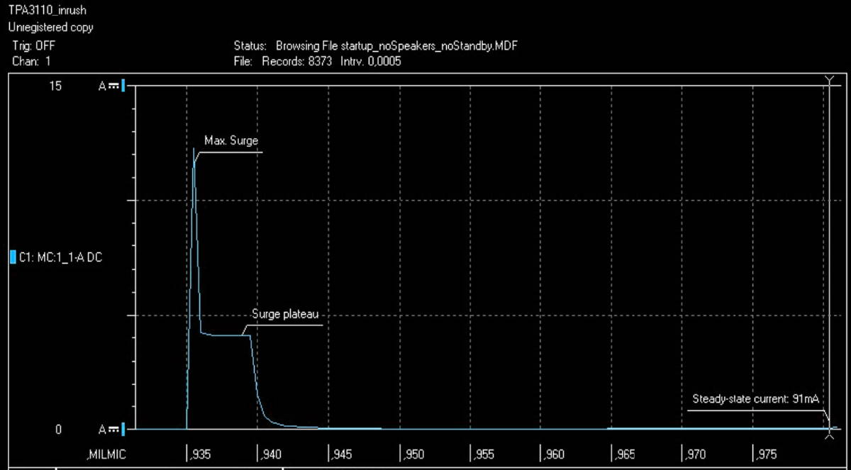
The whole event only took ~10ms, 20 samples. After a really high current spike of >12A, there’s a current plateau at around 4A until the capacitors are charged and the reduces to the circuit’s normal idle level.
The peak current has 1 sample only - I cannot say whether this is an outlier/ measurement error or a real event. Some assumptions for its cause:
- very low ESR small bypass within circuits
- Sample rate still too low
- Current meter range violation
- Power supply current limit engaged creating the current plateau (set to
5Aso it does not really fit)
Voltage @Amplifier’s supply pins
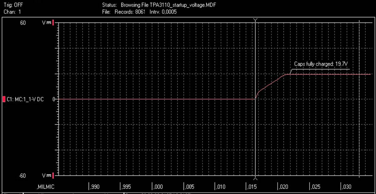
The voltage measurement shows a steep incline for the first sample when the inrush event starts, followed by an almost linear increase until steady state voltage is reached after ~6ms.
These values correspond nicely to the current peak at the very beginning and the plateau showing the capacitors gradually charge until target voltage is reached.
Repetition & Conclusion
I repeated the measurement with different settings: Speakers connected/disconnected, amplifier in standby/idle but the results were identical. This led me to the conclusion that the amplifier IC and its periphery do not affect inrush current - it only depends on the power supply path and its protection, decoupling, and energy buffering function.
Drawbacks of doing this measurement with a multimeter are a limited data rate (I would have liked to measure with 10…100kHz for these surge events), the inability to live-view, and long data transfer times due to a (probably outdated) infrared communication standard. On the other hand, I am now able to do “offline logs” very quickly and without the need of a computer or even mains connection. Setup is easy and device portability is great for field application - I’ll do some more measurements in the future where the multimeter might be an even better fit.
For the amplifier, I will design a protective circuit as already discussed in this post to mitigate issues with USB-PD devices.