Transient Voltage Suppressors
Electronics knowledge article: TVS diode
What is it?
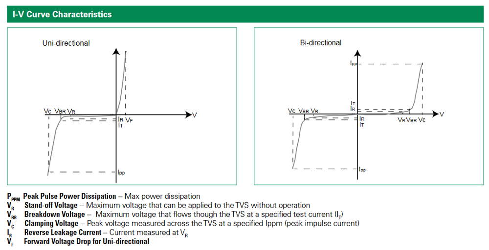
A transient voltage suppressor diode protects a circuit from short-term voltage spikes. TVS diodes are available for different voltage settings, peak currents, and with uni- or bidirectional protection capability.
Differences between TVS and Zener diodes
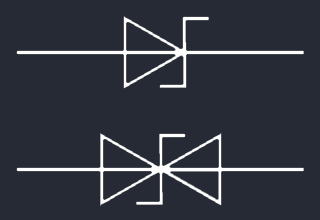
Like Zener diodes, TVS diodes are normally operating in reverse bias direction. They also share the same electronics symbol.
But while Zener diodes are designed to work at their precisely defined breakdown voltage with a constant control current in applications where voltage regulation is needed, TVS diodes normally operate below breakdown voltage as they are protective devices, clamping overvoltage spikes to acceptable levels. They are designed to withstand high peak pulse currents.
Differences between TVS and Schottky diodes
 The symbol for Schottky diodes is just slightly different to Zener/TVS diode’s. They commonly have a lower forward voltage than their silicon pendants and are known for their fast speed of switching. That’s why apart from rectifier circuits, they are often used in reverse voltage protection circuits. TVS diodes share the quick switching behavior and the low forward voltage, but unlike Schottkys they have a well defined reverse voltage threshold.
How to select the correct TVS for your application
For DC applications, a unidirectional TVS schould be fine to use. Select the Stand-off voltage of the TVS in a way that it is a little above your normal operating voltage. Then look at the clamping voltage you get further “down” the line. Is it still below your protected Circuit’s “Absolute Maximum Ratings”? If not, choose a different TVS, make some compromise with the voltage (but don’t exceed the breakdown voltage of the TVS), or use another transient suppressor device like a voltage dependent resistor or similar.