FreeCAD modeling workflow
Motivation
I just received a second order for AnywhereAmps Alpha. My initial prototype already has a new home, so I’ll be building at least three more copies. All the woodworks done by hand would take 4-5h for each copy, so I decided I want to limit the woodworking stuff to the actual building-it-together process that - hopefully - only takes an hour. I’d like to achieve this by having the custom wood parts milled with a computerized numerical control (CNC) machine.
Tools, tools, tools
Such a machine wouldn’t eat the plans I scetched by hand. So I have to familiarize myself with software that is able to transform 2D scetches into a 3D model, and finally another tool to translate the components of the 3D model into paths for the CNC machine to cut my parts. I chose the FreeCAD software to do the 3D work.
Every beginning is hard.
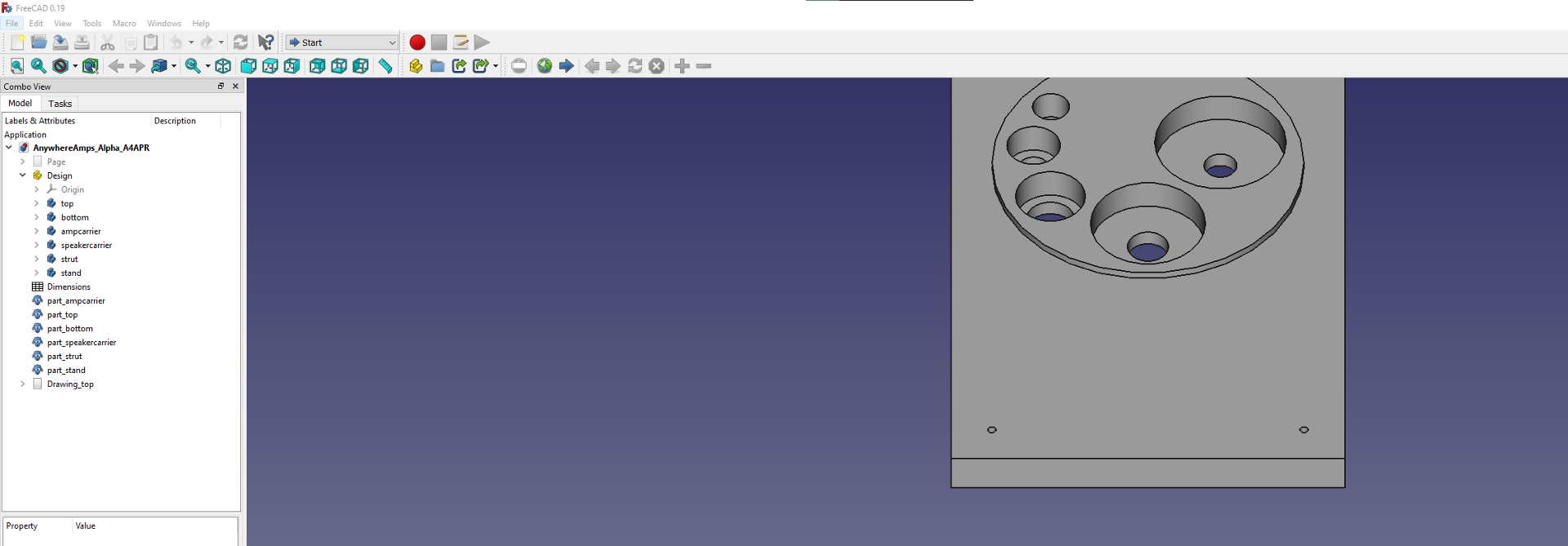
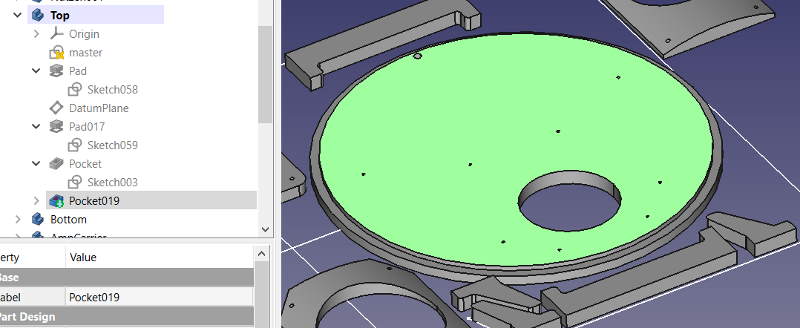
 But FreeCAD… well, I’ll admit that I’m not a CAD designer or mechanical engineer. But still, this tool is hard to get started with. Luckily, there are some quite good tutorials out there like this: youtube link but to be warned, I needed a couple of hours before I had drawn my first part. Plus, what you can see on the image on the right is still a long way before I was done.
FreeCAD workflow
FreeCAD will not tell you how to best work with it. It is a very versatile tool that fulfils many purposes. As I want to use it for drawing 3D parts and/or for G-code generation, I’ll only need a handful of its workbenches.
Of course, the following lines cannot be more than a quick start guide. There are tons of helpful materials out there like a FreeCad wiki, a forum, and many, many tutorial videos etc. at your hands that explain things better and in more detail than I can ;)
Dimensions first - Spreadsheet workbench
Let’s create a central place where we keep all our project’s dimensions. We’ll link them in the drawings, 3D models, and assemblies later so that changing values in the spreadsheet will automatically propagate.
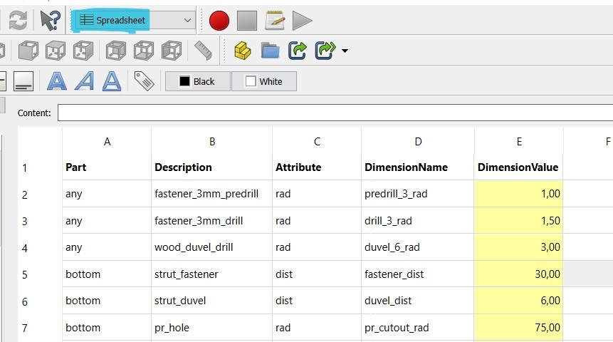
- Select the “spreadsheets” workbench. Create a spreadsheet and rename it e.g. to
Dimensions. - Draw a chart with your dimension’s names. I found it well readable to have a
part_description_attributenaming convention for every dimension. - After entering your dimension’s value, right-click its cell and select “Properties”.
- In the following dialogue, select the “Alias” tab and enter the
dimensionNameyou entered before - In any scetch, drawing, parts design or similar workbench, you’ll be able to use these dimensions under their Alias name. Click “Save”.
Sketch it! - scetcher in Parts Design workbench
It’s time to create a first sketch of your part using the dimensions you just created. You’ll be drawing so-called master scetches fist which contain all elements of a drawing at a specific view, e.g. on the XY-plane.
- Select the “Part Design” workbench.
- Create a new body using the blue lego-ish symbol.
- Create a new scetch for this body using the scetch symbol. Select e.g. the XY-plane.
- Rename your scetch so it’s easy for you to remember its purpose. As your first scetches are the
masterones, I propose to name themmaster_yourPartName_xy - Double-click the sketch and start drawing your shapes.

- Make sure you fully constrain (youtube link) your scetch. Use the dimensions you entered in the spreadsheet to help: Double-click your dimensional constraint and type
=or press the tiny roundfxbutton. Enter the name of your spreadsheet (there is auto-completion, luckily) and then the alias of the dimension you want to constraint to reflect. - Repeat for any dimensional constraint.
With your completed master sketches (one each for every dimension), all information is available for any third party service to mill your parts. If you wanted to do that, you could export your sketches to a dxf file here and you’d be done.
Else: please continue reading.
Create 3D parts - Parts Design workbench
To create an actual 3D part from your master sketches, you’ll have to create derivative sketches that can be extrudes or cutouts. You’ll have to understand FreeCAD’s way of tree-aligning parts and scetches first: Every pad has an underlying scetch that defines how it looks like. Its extruding direction directly depends on the sketch’s plane. Each part can have one or more datum planes where other parts can be attached to, again forming pads, holes, or pockets on that specific face.
FreeCAD will only display the “last” member of your part’s tree, containing all dependant parts you designed before. To toggle visibility, simply hit the space key.
- Create a new sketch in your part’s tree structure. This will be your first
pad, i.e. your actual 3D part. - Choose the
create an edge linked to an external geometrytool (hotkeyX) and select the basic pad of your originating master sketch. - Draw your shape to match this shape and set its constraints, again using the Dimensions spreadsheet you created earlier. You shouldn’t need this too often though, as you linked all possible edges you could find to your master scetch before.
- Now comes the fun part: close the sketch, then hit the
pad a selected sketchicon and enter your dimensions. - Done!
- To create another pad, a pocket or a hole on top of one your pad’s surfaces (called “faces”), first create a new sketch and name it meaningfully. Then click the face you want this scetch to be based on. Finally, choose the “set the Support of a scetch” tool and select the scetch you created before. Repeat starting at step 2. until your part is complete.
Hm, your new pad sits right on the master scetch so you cannot see them any more? Don’t panic, just continue reading.
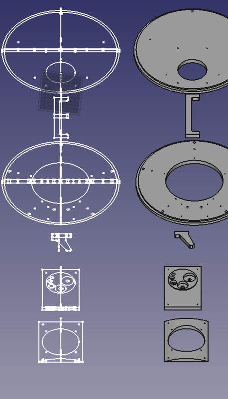
Arrange 3D parts - Draft workbench
In my opinion, it’s a pain to rearrange parts in the Parts Design workbench. It’s getting much easier if you use the “Draft” workbench for this task. You can clone parts easily here as well and arrange them as you deem fit.

- Select the “Draft” workbench
- Choose the pad/part you have been working on before in the parts tree.
- Click the sheep icon to clone your part.
- Make the original pad invisible by hitting space key with the part active.
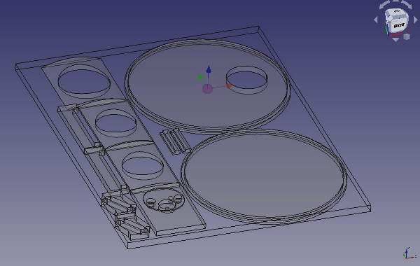
- Choose the cloned part and rename it meaningfully, e.g.
myCoolThing_part. - Select the “move” icon (marked green in above image).
A move consists of two steps: first you have to enter the reference location for your move. Either select the point by clicking somewhere in the 3D view and then moveing the cursor a bit (my recommendation) or enter the reference in the fields on the left, confirming each axis with Enter.
Second, is the actual move vs your reference point. I recommend to enter those values using your keyboard because it’s incredibly hard to move to an exact location using the mouse.
Confirm with Enter, and the move should be complete.
Cool, you now have a dimensions sheet, master sketches that fully specify your parts, the parts themselves as 3D bodies and all properly that’s neatly sorted in your view!
TechDraw: Create a classic “Paper 2D” drawing as PDF
Now, maybe you want to export classic 2D drawings of your part? Luckily, that’s an easy task!
- Select the TechDraw workbench
- Press the
Insert default pageicon. - In the parts tree, select the 3D part you’d like to have drawn
- Press the
Insert multiple views of drawable object(s)icon and select the views you want to be present. - Add dimensions, annotations etc using the tool bar.
- Use the
turn view frames on/offif vertices overlap your geometries, so you can select them again. - Insert cosmetic vertices if you need to, e.g. to draw symmetry lines.
The resulting document might look like this:
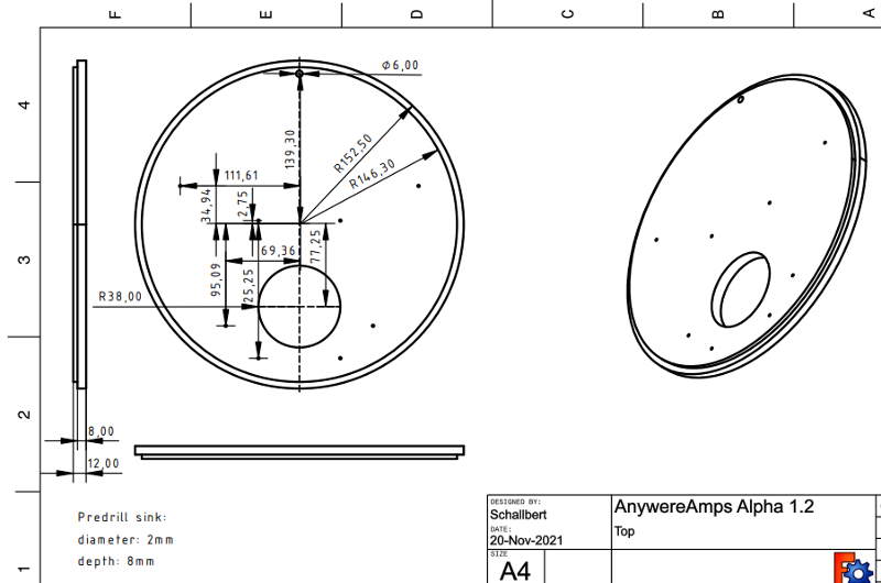
Further information regarding TechDraw workbench can be found in the FreeCAD Wiki.