Working with Aluminium composites
Experiments with Dibond
A friend of mine is currently starting a business. He wanted something to give away to his customers, something that they would remember so they’d return to him. It should not be the standard pen or cup, but something that is somehow more close to what he is doing. Something metally. Something Like a business card, but with a three-dimensional feel. Something engraved.
While searching for material on the internet, I came across aluminium composites - a sandwich material made of two thin sheets of aluminium with a core of polyethylene, also known under its trade names Dibond®, Dilite®, Alcubond® etc. It is available coated, blank or even coloured and, optionally, in different finishes.
“Its PE core is black, so it might be an ideal material for engraving”, I thought.
So I ordered some samples and showed them to my friend. He was blown away, and that’s where this story starts.
The Coaster Concept
We brainstormed about what to do with that material. It should be simple to design and not too large so it could be an easy giveaway.
I know that aluminium composites can be machined in a way that they form 3-dimensional objects (youtube video link). But this seemed to complicated for a start. Our next idea was the one that I’m discussing here:
Engraving Coasters. Round or rectangles with smooth corners, even custom shapes are possible.
I started some tries with engraving cutters that looked promising - but not perfect. The aluminium layer tends to smudge and wants to evade the cutter so it presses into the soft polyethylene core when diving into the material at a 90° angle. Still, my friend wanted me to proceed so I bought a couple of sheets and continued experimenting.
Cutters, speeds and feeds
As the coasters are below 100x100mm, I am using small endmills:
| Cutter (carbide) | Teeth | Dia | Speed | Feed XY | Feed Z | Z+ |
|---|---|---|---|---|---|---|
| [mm] | [RPM] | [mm/min] | [mm] | [mm] | ||
| acryl 30° upcut | 1 | 2 | 24000 | 1600 | 800 | 3 |
| engrave 90°, 0.5mm tip | 1 | 6 | 24000 | 1000 | 500 | 1.5 |
The values may seem a bit aggressive, but I think I need to have a certain speed to not melt down the PE core. Chips do look good - short and thick - with these values and the machine gives a confidential hum when working, so I assume all is fine.
The first part
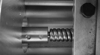
I cut the coaster holder first. It consists of four parts that can simply be put together. They don’t need glue as clearances are tight. I use a fence as orientation for the XY-zero of the workpiece as I want to do two-sided milling. This enables me to do the cutouts as a last step, keeping vacuum pressure on my table until that very last step. Plus, the idea was that I wouldn’t have to manually rework the parts.
The first try was rubbish - front and rear milling paths weren’t perfectly aligned, and as little as some tenths of a millimeter make a great difference here, so I had to fix the root cause (edges on the fence I did not notice before that I had to hone down) and try again.
Here’s the result:

I’m pretty happy how this turned out. I didn’t have to do any manual rework, it just fell out of the CNC like this. But I noticed that the chamfers I added to give the material a smooth touch were pretty different. While the ones on the “rear” that only cut 0.3mm off the edge where the upcut had previously done the part’s cutout were really good while the ones on the other side, where the tool had to cut 0.85mm deep into the material to add the chamfer, were a lot rougher (but still acceptable).
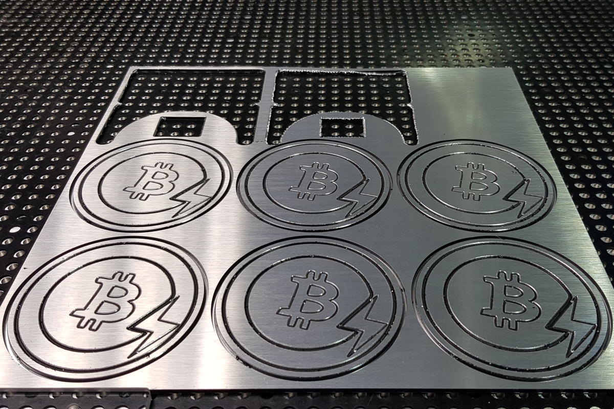
A batch of six
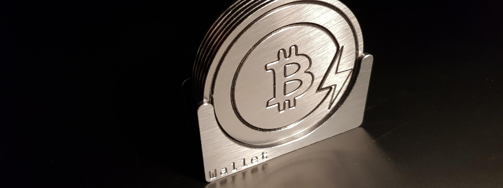
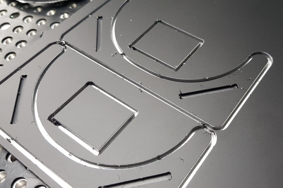
Then I selected a “simple-to-manufacture” logo - the Bitcoin Lightning symbol - and planned some basic engrave paths to have it carved. Here, I also did two-sided milling, which would not fully cut through the material but would leave an “onion skin” at the bottom which would be removed at a second pass on the bottom side while chamfering the edges.
I needed roughly 20 minutes to complete the jobs. Unfortunately, the fence I use to have a defined part edge that would stay in position even if turned around to mill the second side proved to be low repeatibility in terms of accuracy. The cutout on the bottom was off just one or two tenths of a millimeter, which in my case would double the total misalignment when turning it over its diagonal axis. That way, a part of my coaster’s outline had a very deep chamfer while the other half didn’t have a chamfer at all.
I need to find a fix for that. In the meantime, I manually sanded down the edges until I thought it’s enough so nobody would get hurt.
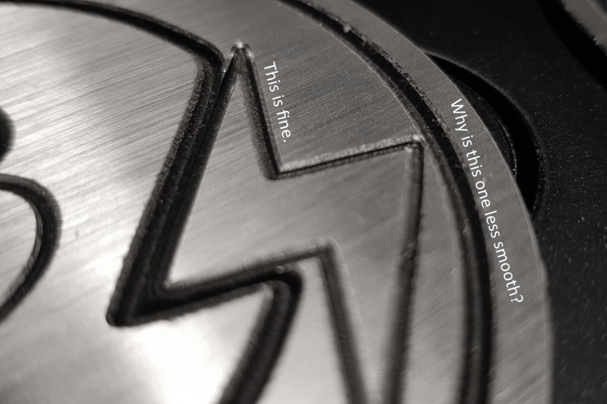
Then, I cleared remaining chips along the engrave paths with a toothbrush, and took the title photo above.
Quality analysis
Upon inspecting the part in more detail, I made the following observations:
All parts look the same
This actually is good news. It means that the tools I bought from vhf this time are still sharp and can be used for future set(s) of prototypes.
It also means that my machine did not experience step losses or mechanical issues and that the workbed surface is level. This is especially important in this case as the 90° engrave cutter’s engage width highly depends on workpiece surface height. With an uneven workbed, the line width would differ visibly from part to part.
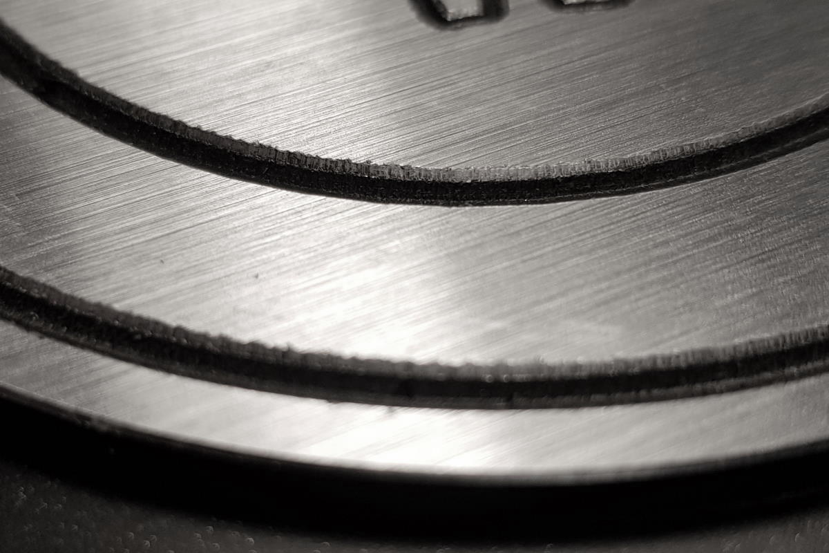
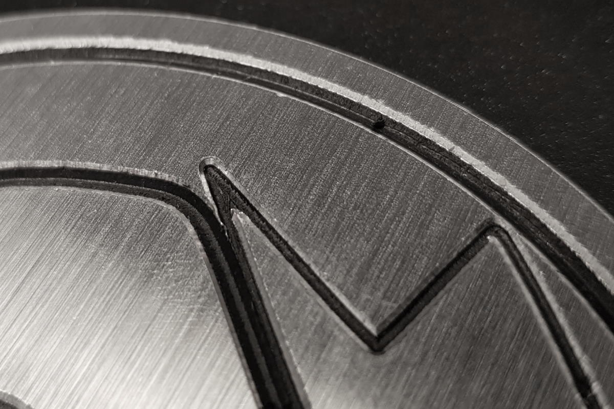
Wide engravings have poorer quality than fine ones
I’m not entirely sure about why that’s the case. I’m no metal cutting mechanic so I’m missing the professional qualification, but my guess is that this is because the engrave cutter does not have a mechanism to get rid of the chips on time, mashing it into the material with its next half-turn which creates a less smooth finish.
If that is the case, an additional smoothing run at a low material removal rate would solve this issue.
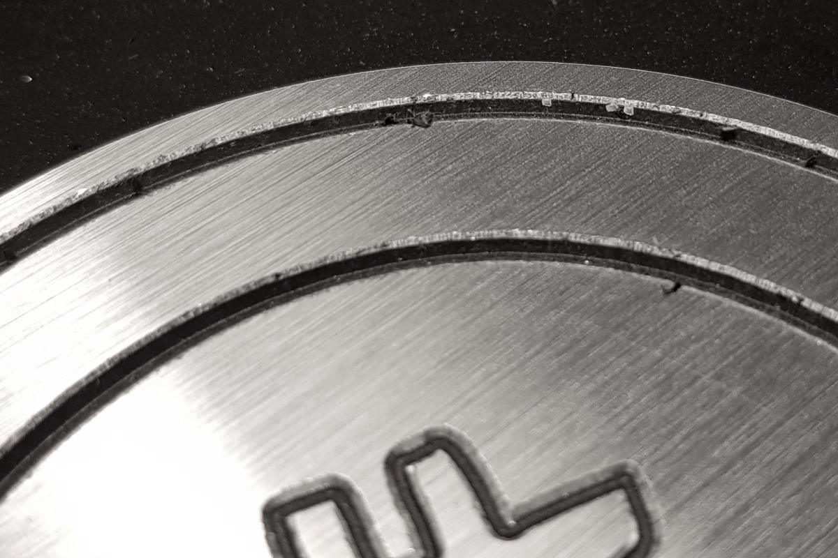
Chamfering without pre-cut delivers less smooth results
My guess is that although the symptom looks different, the root cause might be the same. I’ll try with an additional smoothing run for the other side as well.
Another alternative would be to reduce the feedrate and see what happens. Maybe a balance has to be found between manufacturing time and quality?
I need to get locators to fix workpiece offset
Obviously, I wasn’t able to reproduce part placement with help of the fence when turning the part around. Some tenths of a millimeter are enough to ruin everything.
I could do the following:
- Plan a
Job00that just places locator holes in the workpiece with a diameter of5.04mm. Make sure they are symmetrical so the workpiece can be flipped around the diagonal edge facing to the fence for two-sided milling, while the workpiece edge’s position remains unchanged. - Place the workpiece against the fence and have
Job00executed. - Remove the fence.
- Get some 5mm register pins and put them into the vacuum table’s holes, matching the workpiece’s holes.
Or I could just cut through and manually add the chamfer on the lower side with help of a hand router. As the workpieces are quite small, I’d have to design a holder first to keep my hands safe. Maybe that’s even faster than the above approach…
Some chips are stuck down in the engrave path
I don’t know why that’s the case. Will have to talk to my tool manufacturer to maybe get that sorted out.
Summary
All in all, I can be pretty happy. The machine does what I want it to, and the overall result is OK already now, early in the prototyping phase. The composite material is nice to work with and won’t eat cutters as quickly as other materials (like HPL). The surface finish looks really nice and its “upmarket premium” touch adds to the flair. The chips are a bit annoying, though, because they like to to stick to everything and don’t want to be vacuumed up.
Anyways, the quality ist not fully satisfying yet so I’ll keep adding knowledge and experience to yield some improvements in the future.