Seifenbutler
Project stats
- Difficulty: Medium 3/5
- Cost: ~250€
- Time: 1+ year
The story of Seifenbutler
Accompany me here over a period of more than a year, in which I am constantly working on one project. It goes from an idea with a few requirements to pre-production readiness. I explain my prototype work, go into a little detail about the many setbacks and finally come closer to what I think is a good product.
Idea
May 2022
I recently switched from using liquid shampoo in the shower to solid shampoo and soap. As I didn’t have a tray for the soap, I showered with it. It used up more quickly, didn’t dry for days and stuck to the edge of the shower.
I didn’t want to buy a normal soap holder that would require drilling holes in the tiled walls. So I decided to design a clip-on soap holder for the shower rail. I would mount the piece above the shower head so it wouldn’t be exposed to more water than necessary.
The soap holder should also be easy to fit without tools.
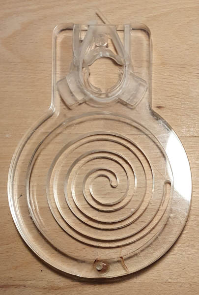
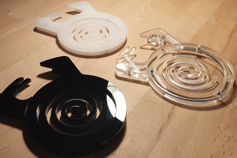
V1-V3: First drafts in HPL
July 2022
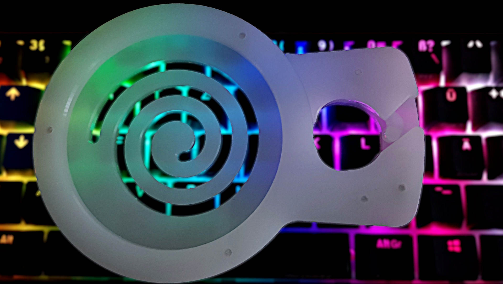
So I designed my own holder. I wanted a simple, round design with a clamp hole to attach to the shower rail and a sunken area to hold the soap or solid shampoo. A few slots in the base would allow water to drip off and the soap to air dry when not in use. I wanted to add a fastener inside the piece and a nut on the inside to reduce the diameter of the hole for the shower rod and clamp seifenbutler - as the piece is called - in place.
To make this possible, it made sense to produce two components - an upper shell that holds the soap in place and provides space for the mounting mechanism and a lower one that has drainage slots for excess water and holds the other half of the mounting mechanism.
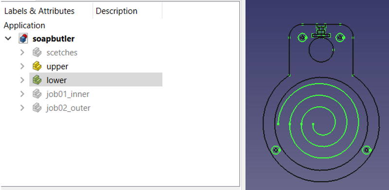
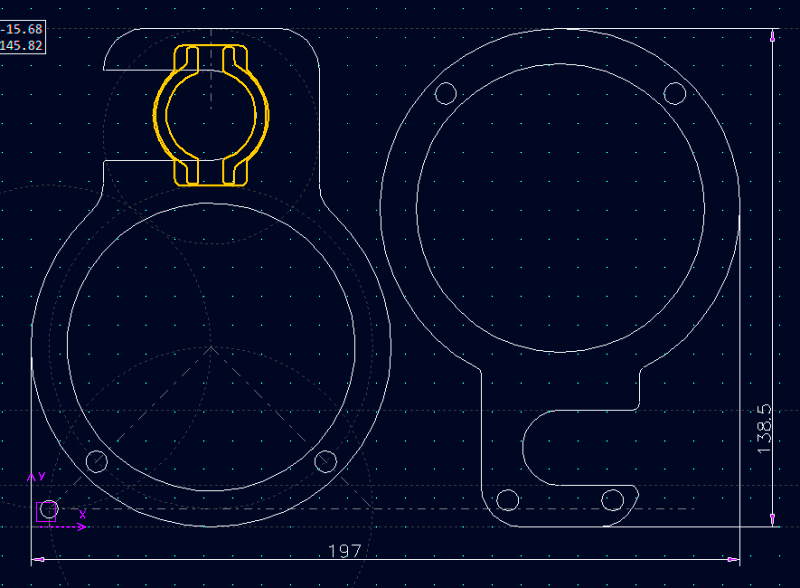
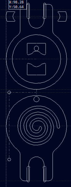
FreeCAD: Sketches
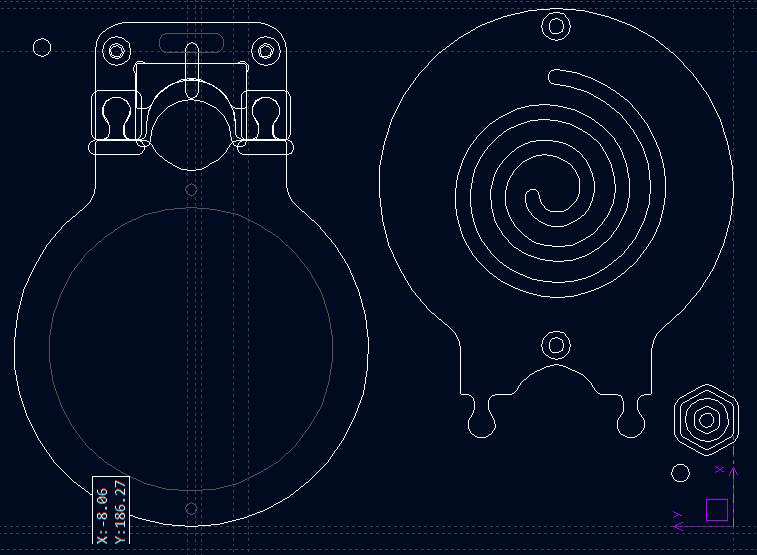
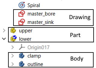 FreeCAD artefacts are organized in a certain way to simplify the handling of different views or to prepare for later two-sided editing using the clone function. Therefore, I first create a series of parts in ‘Parts Design’ mode. Sketches can be grouped into body elements, which in turn are arranged in part elements.
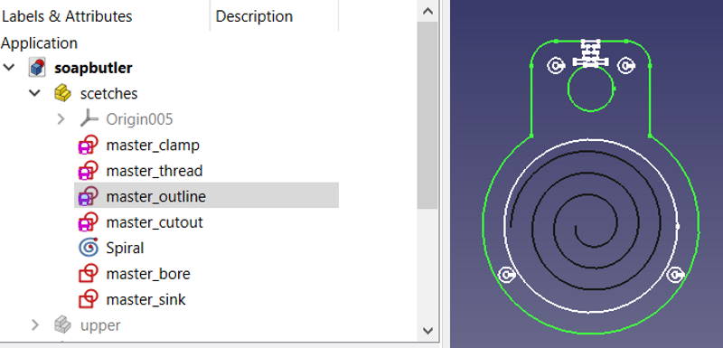
So I create a part (yellow element) that contains “sketches” - all the original drawings (red elements) of all the bodies (blue elements) of the part(s) to be produced. These drawings should be fully constrained. They cannot contain any information on positioning relative to other components. This means that the sketches are all in the same place. Therefore, all inactive sketches should be hidden to avoid confusion.
(A more in-depth description of my FreeCAD workflow can be found in this blog post.)
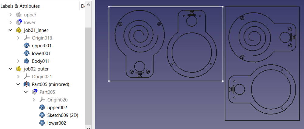
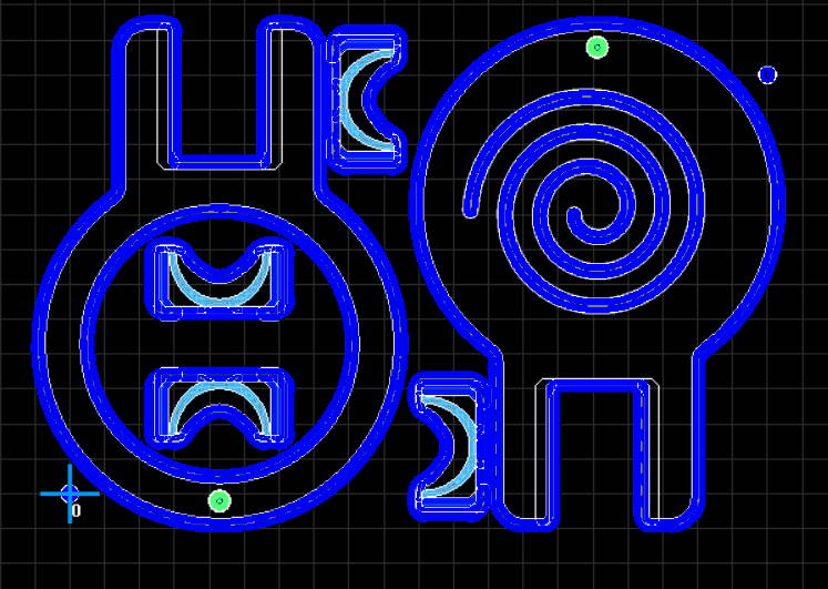
FreeCAD: Parts
Then I create parts that later contain the components to be cut, e.g. “clampingHoles”, “soapButler”, “wallHolder”. They each contain a subset of sketches, but no information on the final positioning. Finally, I create a part for each job that my production has to perform, e.g. job00_clamping, job01_upperMill, job02_3dCut, job03_lowerFinish. These clone body components but add placement information, include mirrored parts for 2-sided milling or provide an outline to set the XY-0 correctly.
The advantage of such a project configuration is that if an original sketch has to be changed for any reason, all cloned parts are automatically changed as well. With clever organization, it is also possible to simply change the dimensions of the parts in the table that then adjust the entire part geometry accordingly without help of the user.
Machining
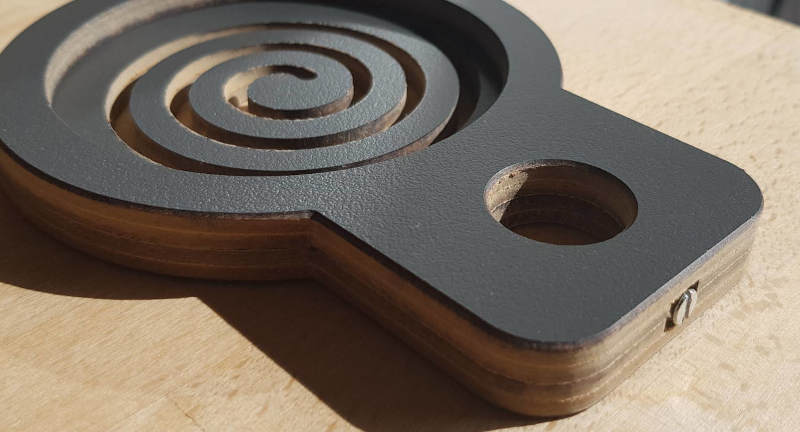
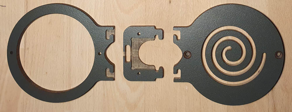
For my first prototype, I chose high pressure laminate as the material as it is very durable, can get wet from time to time and looks pretty good. For machining, I used low helix endmills to keep the vibration under control when cutting the tough HPL material. I opted for coated single flute carbide bits that I bought some time ago (for cutting aluminum). I used eccentric clamps to hold the part in place and only required two additional hold-downs to keep the part on the machine bed.
I had an error in the CAM program that took me a few minutes to fix: I had set the toolpaths for the spiral inward instead of outward. The problem with this is that the spiral becomes increasingly spongy and unstable as the cut progresses. I was only able to keep the vibrations in check by frequently interrupting the milling process and applying tape to the areas where the cut had already been made.
Rating

Production of my first prototype went quite OK. The machine was humming confidently, and apart from a few minor errors (fixing holes in the lower part too narrow, length of clamp fixing incorrectly specified) I was reasonably happy with the result.
It took me about 20 minutes to release the part and remove the taps. This seemed to be clearly in need of improvement.
V4: Failure with cheap HPL
October 2022
 I’ve never used the chamfer function in my CAM before and thought this would be a good opportunity for a test as the part corners were quite sharp on my first prototypes. As I only use a 4mm end mill, the 90°
 10mm chamfer cutter seemed too big, especially as I had to offset outwards to avoid wearing out the cutter’s tip. I therefore chose a 30° tapered bit with only 6mm diameter, which quickly turned out to be a mistake as it hardly softened the corners.
I also forgot that only the outside of the parts would benefit from a beveled edge. I, on the other hand, applied the chamfer to the inside, which was detrimental to the finish quality. I also found that the new HPL sheet I used to make the prototypes was not completely flat, so some parts of the outline were not fully milled through. This in turn led to a lower quality and I had to do considerable manual rework.
V5: Corrections in CAM and better processing quality
November 2022
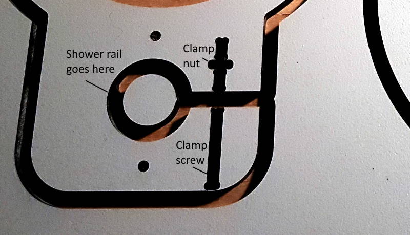
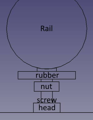 The “free arm clamp” design with open fastening element is not so nice to look at, I guess, because it is asymmetrical. It would also be difficult to clean because of the narrow gap. After some thought, I came up with the solution of a “center clamp”: the fastener would press against a piece of rubber that rests directly against the shower rail to hold the soap dish in place.
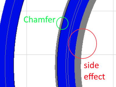
Chamfers
After updating the drawings accordingly, I created another mirrored part in FreeCAD in “Draft” mode. This part clones the original part at the outline and is intended for two-sided milling, rotating the part around its top left edge (XY zero). In this way, the chamfer can be implemented correctly if I can ensure that the XY zero point does not move.
This worked very well in practice, and I was also able to automate the drilling of countersunk holes for the lower fasteners, which increases the build quality. The result can be seen below.
Rating
Unfortunately, after this fifth piece was finished, I noticed that the melamine coating was slightly chipped at the cut edge. I also noticed the smell of burnt material during processing. A quick look at the cutter revealed the cause: it had become blunt after just one hour of use, despite the coating. This makes working with HPL quite expensive and frustrating. In addition, the cycle time for this version was quite long: 15 minutes for one part. That was never going to be economical1.
That’s why I tried to find alternative materials for Seifenbutler. In the meantime, the prototypes should be tried out in the shower for a few months to gather long-term experience. Is HPL suitable for use in damp areas? Does the water creep through between the two layers? Is it easy to clean?
V6: Failure with birch multiplex
May 2023

In my search for new materials, I procured waterproof wooden boards, glued together in multiplex method. As it was considerably thicker than the previously used material (15mm), I simplified the design into a single-piece version with a grub screw at the side to clamp it to the shower rail.
I would drill the hole for the grub screw by hand after production on the CNC.
Unfortunately, however, the material on CNC turned out to be unsuitable for milling the spiral. I got numerous tear-outs and had difficulty holding the workpiece down. The contours of my Seifenbutler were simply too fine for the cross-glued material. Maybe the wood’s fiber length was too high, too.
The five machined parts went straight into residual waste.
V7: Failure with Aluminium-Composite material
Juli 2023
With this design, I returned to my two-component setup and wondered whether Aluminium composite would be a suitable material for Seifenbutler. It is known for its durability and is often used outdoors, at least.
Without further ado, I drew up some new sketches2 that tried to take properties of the new material into account. The light material would finally make it possible to use magnets to hold it in place, so I made appropriate countersinks in the frame.
I had the idea of creating a part from each side of the shower rail and then holding it together using the magnets - this finally got rid of the annoying clamping screw and gave me a very simple design.
Unfortunately, however, the concept turned out to be completely unsuitable. The holding force of the magnets is not high enough and the clamping only works by tilting the soap holder forwards, which gives a strangely crooked impression on the shower rail.
So: keep tinkering!
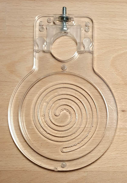
V8: Switch to acrylic glass, chuck
July 2023
After many hours at the computer for the design, I came up with a new clamping principle, copied from the drill chuck of my hand drill: three movable clamping devices mounted at a 120° angle - brought together by means of a cable tie - would hold shower rails of any diameter known to me.
Manufacturing
I encountered various difficulties in production, mainly caused by per design small components, which also had to have notches to guide the cable ties. In addition, I realized that designing and producing smooth fits without noticeable play was a major challenge for me and that it would take a lot of unsuccessful attempts before I reached my goal.
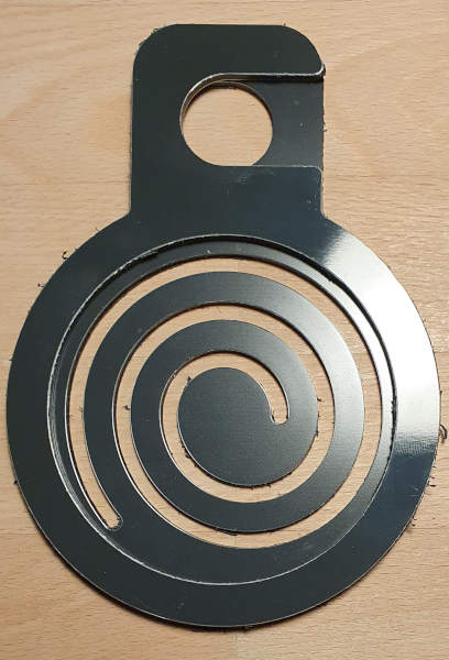
However, by using different sized (2mm, 4mm) milling cutters and optimizing the milling sequence, I was finally able to produce the parts successfully and in good quality. See my article on milling small parts for reference here. Only the spiral is still giving me a headache, because even in acrylic glass it would prefer to avoid the milling cutter. As a result, its edges are quite sharp and uneven.
 Fortunately, it was easy to assemble - It only needs one screw and some plastic glue.
Test
I had this variant in my shower for a few months as a test. As the screw was only galvanized, it unfortunately started to corrode. Note: use stainless steel.
The stability of Seifenbutler could still be improved. The cable tie leaves a little play, so that with little effort, inclinations of around 10° to the vertical of the shower rail are possible, causing a lot of creaking between the upper and lower parts. This needs to be improved.
I would also like to simplify the clamping mechanism again.
V9: Cast acrylic glass, removable soap tray
July 2023
This evolution step holds upper and lower shells together at the front with magnets that can be invisibly sunk into the material. There are two inserts in the clamping area at the back, which fit into a suitable recess in Seifenbutler like a drawer and hold it together.
It took me several prototypes to get the tie guide to the point where the cable tie is simply inserted into the back of Seifenbutler, wraps itself around the shower rail and finally reappears where it is ready to be tied down.
This is the first design that meets my requirements in terms of holding power and ease of assembly. Unfortunately, the production is complex and the tolerances have to be kept low, as the soap holder either slips out of the clamp too easily or can hardly be fitted because the fit is too tight.
Soapbutler zip tie demonstration
V10: Improved manufacturing process
August 2023
With a few optimizations, this version corresponds to V9. I achieved better repeatability in manufacturing and I could be a little more generous with tolerances for fits.
With this design, I obtain first feedback from a couple of friends. The unanimous opinion: cable ties look like a makeshift solution so customer acceptance might be low.
So I head back to the drawing board.
V11: ‘L-nose’ plug-in system in HPL
August 2023
Another attempt in HPL, this time with multi-tooth cutters. They rasp the material rather than cutting it and are designed for processing abrasive, fiber-rich materials such as CFRP/GRP. However, the high toughness of HPL combined with poor heat dissipation means that the milling cutters become completely blunt after just two prototypes have been produced. So they are not a solution for efficient work in HPL for me either.
The design is again multi-part and achieves the clamping in its last update via a rear-mounted screw, which is tightened after the front and rear parts have been put together. This makes the soap holder longer overall, which I don’t find ideal in terms of design.
On the other hand, I think I now have a good handle on the manufacturing quality. The cuts are clean and the quality of the edges is also very pleasing.
Due to the rapid cutter wear, it is very difficult for me to produce a slight oversize fit for the plug-in connection. It happens all too easily in my attempts that the cutter loses diameter too quickly and that parts cannot be inserted into each other at all or only with brute force.
Perhaps I can solve this problem by using a different fitting geometry?
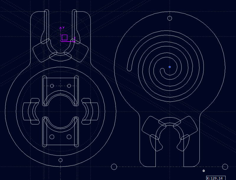
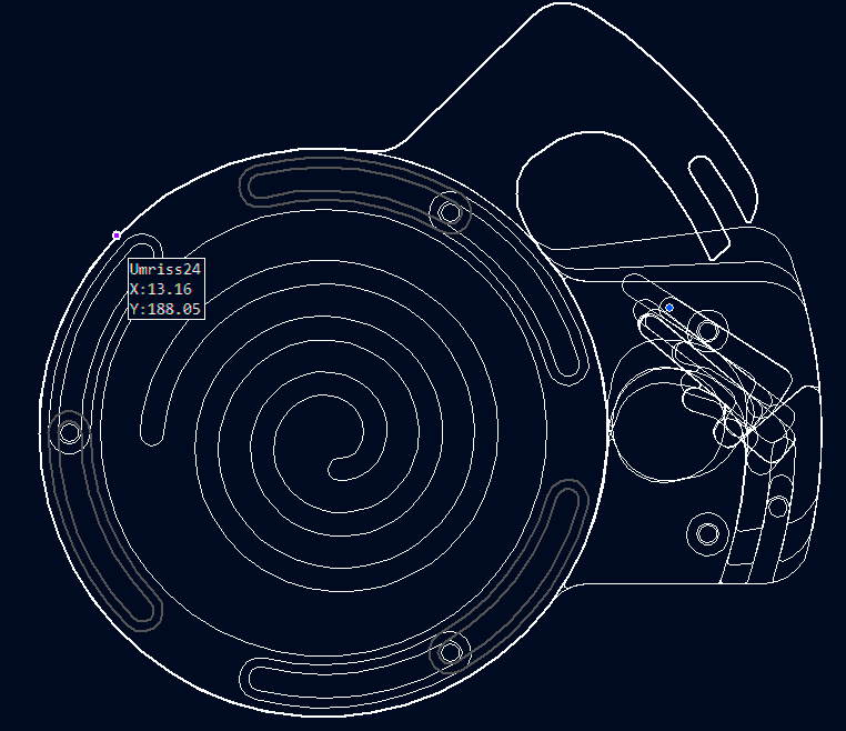
V12: ‘Brio’ plug-in system
September 2023
Here I use acrylic glass again, this time in the extruded version. This way, thickness tolerances are very small compared to the cast version and my Z-zero points always fit. This is great for applying chamfers, which are finally the same width on every part and give the material a high-quality finish.
Now I also have a solution for the spiral: double-sided processing. This increases the workload for me, but I’d rather spend more time at the machine than be annoyed about poor quality later on.
 My procedure: I mill the spiral almost all the way through and leave only a delicate
 0.3mm. I then use the chamfer cutter on the back and cut the spiral from inside to outside. I also secure the underside with adhesive tape so that my vacuum table can hold the spiral securely and vibrations are avoided.
The design includes a knurled screw so clamping can be done without tools. As the clamping exerts strong tensile forces on the connectors and they therefore have to be positioned in the axis of the shower rod for stability reasons, I also have a slight tilting problem here. This problem increases the smaller the diameter of the shower rail is.
I was able to avoid tilting with another variant, but then the spigots are no longer covered. This in turn means that shower water can now get in there and leave residues.
I’m almost there. Nevertheless, there may still be something I can improve.
V13: Automatic clamping and zero series production
October 2023
In version 13, I try to bundle the advantages of the previous versions V9-V12 while avoiding the disadvantages (tilting, cable ties, assembly with tools, unstable) as much as possible.
New clamping concept
I am therefore pursuing a new clamping concept. I still want to take most commercially available shower rods into account during installation and therefore need to clamp securely between 18mm and 25mm. From the previous versions, I have also realized that additional pressure must be exerted centrally behind the shower rail to prevent Seifenbutler from tilting.
I am also trying to realize the locking mechanism around the shower rail by means of a rotary movement. Pivot point is the center of the spiral, which requires three additional screw connections around the circumference of Seifenbutler. With V13.9 I finally achieve the breakthrough.
The automatic clamping mechanism is activated by pushing upper and lower shells together so that Seifenbutler adjusts continuously to the diameter of the shower rail. It is locked in place by a knurled screw on the underside, where an inclined plane on the catch hook prevents unintentional opening.
Manufacturing
Unfortunately, this design is very complex. It consists of five components made of acrylic glass, five screws and a knurled screw with spring washer. It takes quite some time to assemble.
The work on the CNC takes over 10 minutes per part, which is a lot. I also have to use consumables due to the required workpiece hold down.
Nevertheless, the manufacturing quality is higher than ever before and Seifenbutler is now child’s play to fit without tools and within a short time.
Conclusion
January 2024
Looking through my CAD files, I have planned a total of 42 versions of my soap holder so far, divided into 13 designs, some of which are very different. 21 of these versions have actually made it onto the CNC in the end and 5 of them have been produced in larger quantities than 3.
I have four Seifenbutlers in my shower for endurance testing and they are now used by the whole family.
I can’t really count the number of hours I’ve spent on the subject so far - but it’s been many. I’ve learned a lot about materials and their suitability for different part geometries, absorption of forces, their machinability and the necessary cutting values on my machine. And also that it’s worth pursuing things with determination over a long period of time. Not in monetary terms, but definitely for me as a person.
I don’t want to rule out making further optimizations to the soap butcher - but first I want to see whether it is marketable as a niche product in the near future.
-
I give a deeper dive into the challenges of machining HPL in this blog post. ↩
-
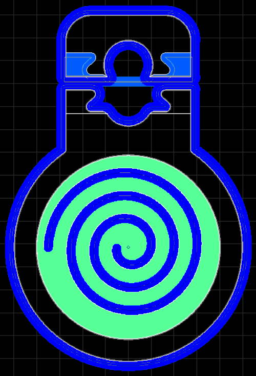
As you can see from the CAD images from here on, I changed my drawing software (from FreeCAD to CADasCAM). Despite some disadvantages, it is easier to use for 2D drawings and I get results faster. One big downer: CADasCAM is not open source 😥. ↩