Breadboard Fireplace
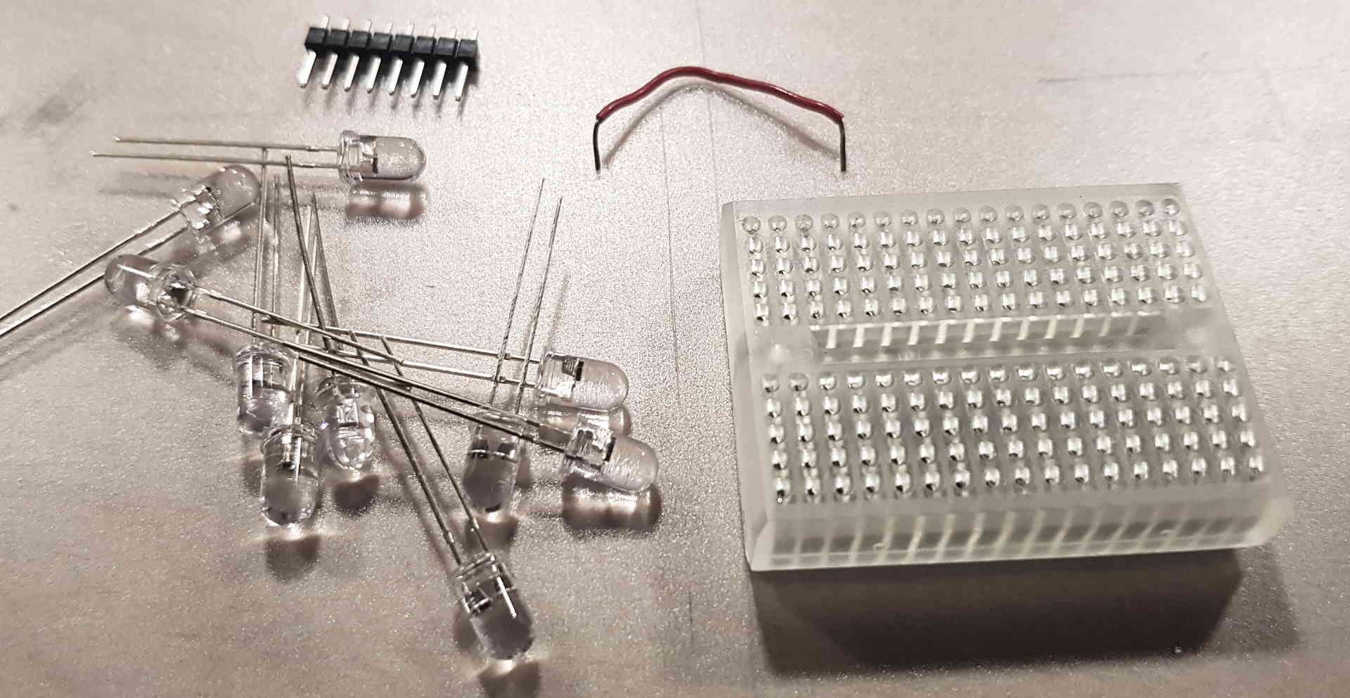
Material list
| Item | Count | ~ Cost [€] |
|---|---|---|
| LED: Warm-white, e.g. Ifwd=30mA, 3lm | 5 | 1,50 |
| LED: Yellow, e.g. Ifwd=35mA, 1lm | 2 | 0,60 |
| LED: Red, e.g. Ifwd=35mA, 0.4lm | 1 | 0,30 |
| Arduino Nano Atmega328 | 1 | 18 |
| Breadboard e.g. 170 pins | 1 | 0,70 |
| Jumper wires, pin-pin, e.g. 5cm | 10 | 3,30 |
In addition: Some jumper wires, Mini USB cable, powerbank / wall adapter
Tools
- optional: hot melt gun
- optional: soldering iron
The Build
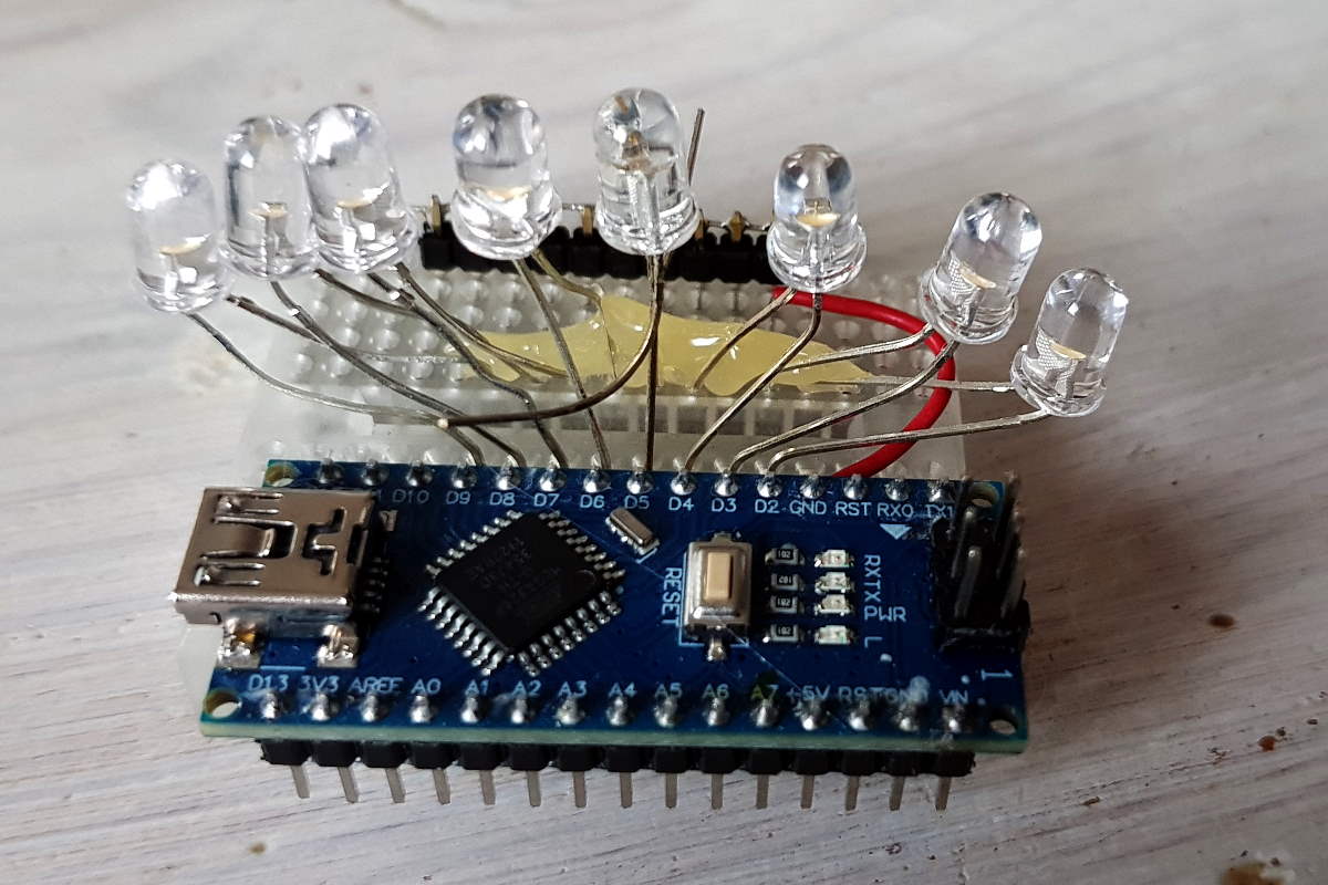

- Connect the Arduino Nano’s right header to the left hand side of the breadboard. Make sure all pins are on level. If possible, don’t touch the pins due to risk of electrostatic discharge that may damage the device.
- Connect the anodes (
+) of the LEDs to the board’s outputsD2 through D9. The anode most often is the LED’s pin that doesn’t carry the chip (left in this case). - Place the cathodes (
-) of the LEDs to the right hand side of the board. - Place the header to the right of the LED’s cathodes.
- To connect the cathodes, user jumper wires. Alternatively, solder the cathodes together right away.
- Using a jumper wire, connect the “common cathode” to one of the
GNDpins of the microcontroller board. - The LED anodes shouldn’t be able to touch each other. You can ensure this by placing some hot melt at their legs.
Programming
The code is so simple that I can just paste it here. Copy it into your favourite IDE, program your board and you’re done!
Disclaimer: This piece of code is “quick’n’dirty” and has lots of potential for refactoring. For instance, the pin IDs are hardcoded, I’m not using C++11’s range-based loop, and the speed algo will hit the low limit quite often and not show random behavior.
I’m happy to hear your suggestions on my Github discussions page.
#include <Arduino.h>

#define MAXLONG 0xFFFFFFFF
#define SPEED_HIGHLIMIT 1000 // 500Hz
#define SPEED_LOWLIMIT 0x1FFF // 20Hz

void calcFlicker(uint32_t randomFlicker);
void writeLed(uint8_t columnCode, uint16_t speed);
uint32_t iRNG = 1;

void setup()
{
    randomSeed(analogRead(0));
    pinMode(2, OUTPUT);
    pinMode(3, OUTPUT);
    pinMode(4, OUTPUT);
    pinMode(5, OUTPUT);
    pinMode(6, OUTPUT);
    pinMode(7, OUTPUT);
    pinMode(8, OUTPUT);
    pinMode(9, OUTPUT);
    iRNG = 1;
}

void loop()
{
    iRNG = (iRNG >> 1) ^ (-(iRNG & 1u) & 0xd0000001u);
    calcFlicker(iRNG);
}

/*
    This function takes a 32bit random value,
    and moves this value along a window of an 8bit
    flicker output value.
*/
void calcFlicker(uint32_t randomFlicker)
{
    uint8_t currentFlicker = (uint8_t)(randomFlicker & 0xFF);
    uint16_t randomSpeed = min(SPEED_LOWLIMIT, (uint16_t)(randomFlicker & SPEED_HIGHLIMIT));
    for(uint8_t i = 0; i < 24; ++i) // 24 because of 32bit length of random, may not run empty
    {
        writeLed(currentFlicker, randomSpeed);
        randomFlicker = randomFlicker >> 1;
    }
}

/*
    this function outputs a code to an LED column of 8 LEDs
    connected to arduino's pins with a selectable delay.
*/
void writeLed(uint8_t columnCode, uint16_t speed)
{
    digitalWrite(2, columnCode & 0x01);
    digitalWrite(3, columnCode & 0x02);
    digitalWrite(4, columnCode & 0x04);
    digitalWrite(5, columnCode & 0x08);
    digitalWrite(6, columnCode & 0x10);
    digitalWrite(7, columnCode & 0x20);
    digitalWrite(8, columnCode & 0x40);
    digitalWrite(9, columnCode & 0x80);
    delayMicroseconds(speed);
}
Working
Once you power the device up via USB, the LED flicker sequence should start and all LEDs should light up eventually. You’ll notice how the glow calms you down. Maybe you have some twigs ore firewood at the ready and an empty space in your shelf? Take a powerbank and hide your Breadboard Fireplace below its wooden decoration. You’re done!