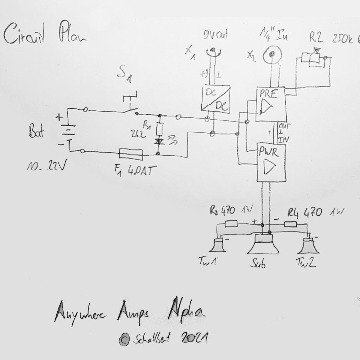
AnywhereAmps Alpha
Plans


Lists
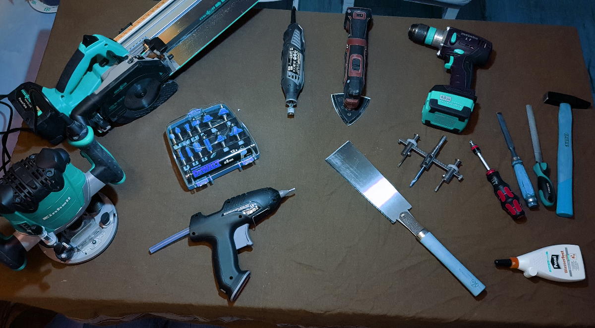
Tools
| Tools needed |
|---|
| Power drill |
| Router, compasses mount |
| Multi-tool: Sanding, Wood cut, cutter head |
| hand-held or table circular saw with guard rail |
| Hand saw, fine |
| hole cutter d>=100mm |
| Chisel, 12mm |
| Hammer |
| Screwdrivers, bits |
| Wood drills: 3mm, 4, 5, 6, 8, 10, 12mm, counterbore 45°, Forstner 30mm |
| Steel drills: 4.3mm, counterbore 45° |
| Cutter heads: 8mm straight, 12mm straight, 45°/d12mm optional |
| Soldering iron, solder, shrinking tube, hot melt, 2m of 0.75mm² cable etc. |
Material list
| Item | Size [mm] | Count | ~ Cost [€] |
|---|---|---|---|
| Shell: Poplar Multiplex | 12” x 6” x 7mm | 1 | 62 |
| Top/Bottom: Poplar Multiplex | 12” x 12mm | 2 | 8 |
| Speaker adapter plates: Poplar Multiplex | L 300 B 150 W 12 | 1 | 2 |
| Amp holder plate: Poplar Multiplex | L 160 B 95 W 12 | 1 | 1 |
| Strengthening & Mounts: Birch Multiplex | L 220 B 30 W 12 | 4 | 2 |
| Screws (preferably Torx) | 12 x 3 | 20 | 2 |
| Screws (Battery holder, handlebar) | 16 x 3 | 12 | 2 |
| Screws & nuts, PCB holders, washers | 15 x M4 | 8 | 2 |
| Foam Seal | 2000 x 9 x 3 | 1 | 6 |
| 1/4” Input Jack | 50 x 12 | 1 | 3 |
| Power switch with LED, 250VAC 4A | 1 | 3 | |
| Potentiometer 250k log 6mm axis + Volume knob | 22mm diameter | 1 | 5 |
| 9V Output Barrel Jack | 5.6 brl, 2.4pin | 1 | 2 |
| Fan grill (protective speaker cover) | 120 x 120 | 1 | 1 |
| “I-Type” Foam Seal (Speaker) | 600 x 9 x 2 | 1 | 2 |
| Aluminium Enclosure | 143 x 72 x 43 | 1 | 4 |
| Class-D power amp board, e.g. TPA 3110 | 70 x 100 + 22 | 1 | 16 |
| Piezo Tweeter, e.g. Monacor MPT-005 | 85 x 85 x 72 | 2 | 12 |
| 4” Woofer/Mid speaker, e.g. Visaton KT100 V 4Ohm | 99 x 99 x 52 | 1 | 25 |
| Battery, 10V - 18V | What you prefer | 1 | ? |
| Electronics parts for Circuit Board, fuse… | 1 | 10 | |
| Spare wood e.g. as mask, template, helper | e.g. 300 x 300 | 1 | 0 |
Electronics parts on the circuit board
| ID | Item | Type | Value |
|---|---|---|---|
| R1 | Resistor | 0207 | 100k |
| C1 | Elko | RM=2 D=5 | 1 µF |
| C2 | Elko | RM=2 D=5 | 4.7 µF |
| R3 | Resistor | 0207 | 10k |
| R2 | Resistor | 0207 | 100k |
| - | Header Male | 2-pin | - |
| - | Header Male | 4-pin | - |
| - | Header Male | 2-pin | - |
| C1 | Elko | RM=2 D=5 | 2.2 µF |
| R4 | Resistor | 0207 | 10k |
| IC1 | NE5532 | DIP-8 | - |
Jumper wires
| From | To | length [mm] |
|---|---|---|
| (11/1) | (11/2) | 2.54 |
| (10/3) | (10/1) | 5.08 |
| (14/6) | (14/2) | 10.6 |
| (8/1) | (8/6) | 12.7 |
| (9/2) | (9/5) | 7.62 |
| (3/2) | (3/0) | 5.08 |
| (22/0) | (22/1) | 2.54 |
hole (x/y)
The Build
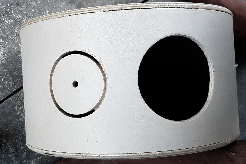
Cut holes
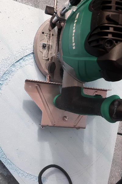
 Warning When using the hole cutter in a hand tool, be very careful - I think it is one of the more dangerous tools. It is best applied gently with very low pressure and relatively high speed of
 >300rpm. Use a torque support and your drill’s torque limiter. Make sure the cutter’s heads are properly fastened and the workpiece is very well secured. Prepare for sudden kickbacks and mind the high intertia torque of the heavy tool.
- Prepare the board for the speaker adapter plates as shown in “Plans”
- Prepare the shell: Mark the middle of its height and draw a helping line on the outside. You might want to use a scale tape to account for the curvature. Then mark the three hole centers. I propose a
125mmgeodesic curve between them. - Prepare the top circle for the controls panel cutout.
- Choose a hole diameter of
75mmon your hole cutter. - Cut two holes for the tweeters into the adapter board. If you flip the board when you’re half through, the quality of the hole’s edges will be weigh better.
- Now cut the two holes into the shell. Be very careful here, you can easily kill the inner surface if you cut at too low speeds or apply any vertical pressure.
- Cut one hole in the cabinet’s top panel that you prepared. I used
76mmbut nevermind, keep the75mm. - Change the hole diameter on your cutter to 92mm and repeat for the Low/Mid speaker.
- Repeat this cut as the shell’s center hole.
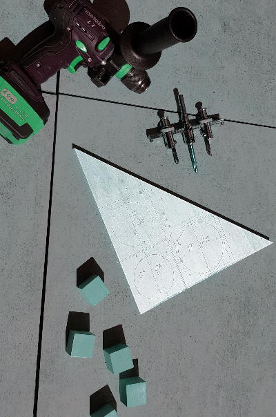
Routing
- Put your shell onto the board you’re going to cut top and bottom of the cabinet from. Transfer its inner and outer diameters onto the board.
- Find the center of this circle, e.g. by using the method 3 of this guide.
- Mount the compasses tool onto your router, use a
12mmstraight cutter head. - Cut the “inner” circle for the notch. I’d propose a depth of
4mm. - (optional) Mount the
8mmcutter head. - Cut the “outer” circle in a couple of steps until you have the full depth of your board cut.
- Turn the circle around, and with e.g. a radius cutter, chamfer the edges.
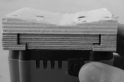
Carving
 Both the adapter plates and the battery mount sit at the shell’s inner/outer diameter, so they need to be curved to be a perfect fit. With hand tools, getting this right is kind of a challenge.
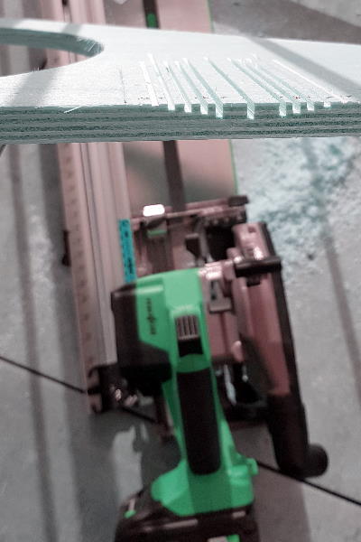
- Measure the cutting depth needed so that when connecting the cuts, a curved surface will be created.
- For the adapter plates, take the inner shell diameter, for the battery mount, use the outer. Note that the speaker adapter plates are convex while the battery holder has to be concave.
- Use your circular saw to make these parallel cuts. Mind the blade’s width.
- With a chisel, connect the cuts. Try to work along the grain of the different layers.
- Use a belt sander, your multi tool, or a rasp to smooth out the curvature until it’s a good fit.
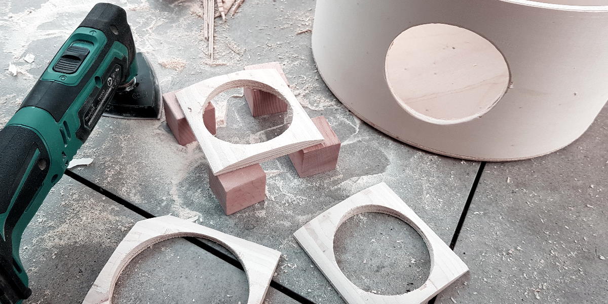
- Atach the adapter plates on the inside of the shell using wood glue.
- Make sure alignment of the holes is good, then take some hot melt to fix and seal the adapters while the glue is setting.
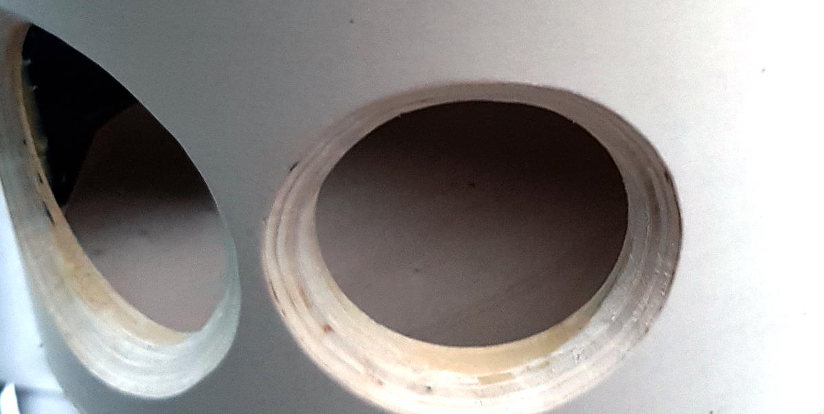
- After some hours, either smooth out if the overlap is not perfect or take the
45°cutter head and create a chamfer. I found this to be the least controllable bit of the whole build because the router wouldn’t sit properly on the curved surface, creating rippled edges. I had to do quite some rework with the multitool.
Additional wood works
Copy the amp carrier Board’s dimensions from the plans section. Use a Forstner drill or the hole cutter to mill the ditch for the potentiometer. A depth of 6mm should be enough to properly mount the potentiometer. For your switch, a countersink might be good to get the diameter just right so that it fits in snugly. Finally, cut the holes for the jacks.
 As there are a lot of battery types around, I didn’t create a specific design for the slider and battery contacts. I just used the typical crimp connectors and glued them in the adapter plate so they can establish a good electrical contact to battery plus and minus. As my battery does not have the latch included, I had the slide gradually increase thickness like a wedge so that the battery would “stick” at the correct place.
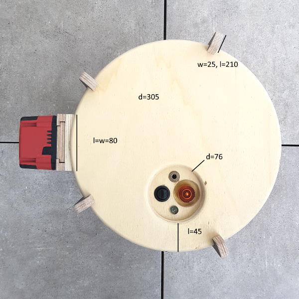
I cut some wooden rods to keep top and bottom of the cabinet closed, and at the same time protecting the wooden surface from bumps. Their length is 25mm more than the total height of the cabinet, and their width is 25mm respective 12mm at the cabinet sides.
Electronics
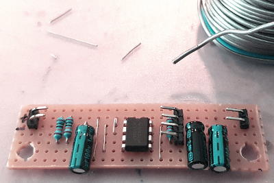
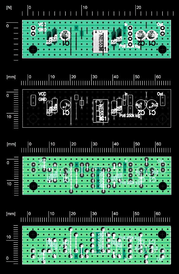
- Cut and drill the circuit board as described in the Plans section. It is a good idea to print the plan at scale so you can use it as a mask.
- Place the conductor breaks. You can use a
3mmmetal drill and hand-cut them if you have no extra tool to do this. - Craft the jumper wires and place them. Use the jumper list as reference.
- Place the resistors.
- Use some tape to fix the parts at the circuit board, flip it, and start soldering.
- Place the capacitors. Mind that you might not have enough space in your housing so that you want to have them mounted horizontally.
- Now place the other components and repeat fixing and soldering them.
- Prepare all connections and wires to the board: Potentiometer, source in, power amp out,
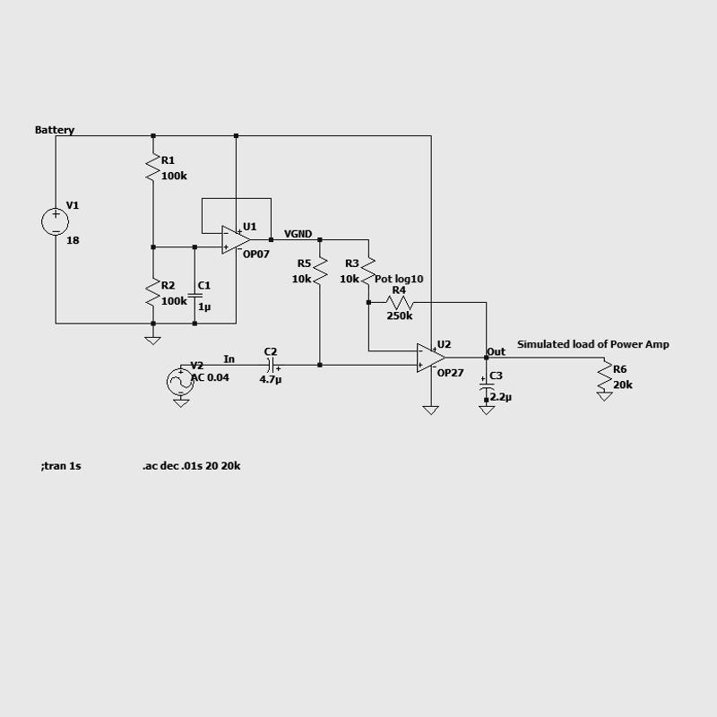
VCC/GND - Check if the power supply section is working. When connecting only
VCC/GND, it should draw between2mAand10mAof current depending on potentiometer position and supply voltage. Make sure to avoid reverse polarity, the NE5532 is killed easily (trust me, I know!). You should measureVCC/2when you probe the virtual ground Op-amp stage’s output. - Check the gain stage. If you have an oscilloscope and a function generator, it should be an easy thing to do. If you don’t, connect the input to an audio source, e.g. your smartphone and the output to a
2k2resistor, in series to an LED and a diode like 1N4148 or 1N4007. Turn your smartphone to full volume. The LED should start flickering when turning the resistance of the potentiometer up. At which position flickering starts depends on the LED’s forward bias, your supply voltage and your source’s maximum output voltage.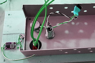
- I propose to mount all the electronics and the audio input - except the
9Vsupply regulator - in a metal enclosure to reduce electromagnetic interference. Depending on your power amp’s wattage, you might need passive or even active radiators. For me, some holes in the enclosure will do fine. - Mount the enclosure to the amp adapter plate.
- Cut holes in the enclosure as indicated on the adapter plate.
- Insert switch, potentiometer and jacks. Solder the connecting wires.
- Add a fuse, e.g.
4.0Ato the setup on the negative path to battery for added safety. - Mount preamp and power amp and connect them properly.
- Test it! E.g. use an old speaker of yours. Without any source connected, you should hear only so much as a little hissing from the speaker at full gain. When you connect your smartphone, start with gain at
0and low smartphone volume. Then increase the preamp gain to check if the setup works fine.
Putting it all together
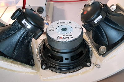
- Mount the speakers. Use hot melt or a foam/rubber seal to make the connections airtight
- Use hot melt to close any holes left, e.g. for the screws.
- Solder the tweeters in parallel to the Bass speaker and connect the output cable from your amplifier.
- Mount the battery holder and connect its wires to the amp’s terminals.
- Put the seal around top and bottom plate so that no air can escape when mounted.
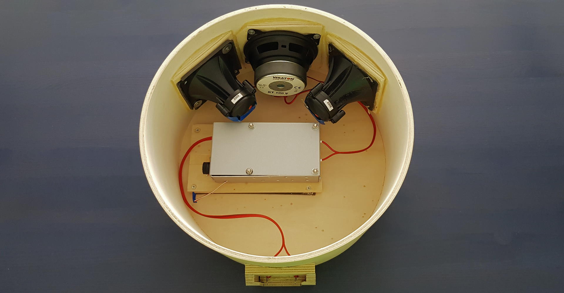
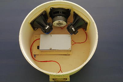
- Flip the assembly and put the “top” plate with the amplifier on it in its place like shown on the picture.
- Make sure that none of the speaker terminals touches the amplifier housing, risk of a short-circuiting the power amp.
- The simulation shows that the Bass reproduction will improve if you add damping wool. I slayed an old cushion to get some.
- Close the cabinet and fix it with the wooden stands you prepared earlier. Or use screws instead.
- You’re all set (for now)! You earn an applause! Doesn’t it look gorgeous? But sure you’ll want to give it a try…
Fine tuning
- Too much treble? Check how much higher the sensitivity ratings of your tweeters are compared to the Bass chassis. If it’s not on par, solder 1W resistors in series to the tweeters. I have ratings of
96dB@1W/1mvs80dB@1W/1maccording to the chassis’ technical data. So I’d have to get the tweeters a lot quieter. I tried with an1kpotentiometer and finally selected a resistance of470Ohmwhich sounded just right. - The Bass flutters at high volume? Most likely, your cabinet is not airtight. Put on a test tone, e.g. 35HZ youtube link, and check if you hear or feel where the air is coming through. Fix the leak(s).
- Your 9V switching buck converter emits noise into your amplifier setup? Try smoothing it with a
100nFcapacitor, and maybe add a10kparallel resistor to create a dummy load. If this doesn’t help, take a linear converter instead like LM7809. As it dissipates much more heat than its switching colleague, plan for mounting it to your metal enclosure.