Meine Platinen sind angekommen!
Fortsetzung des Artikels PCB Hardware Design
Lieferung
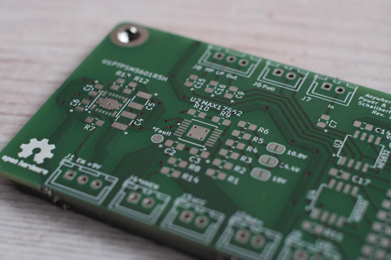
Nach weniger als zwei Wochen sind meine Platinen endlich angekommen. Zusammen mit allen Teilen, die zum Löten benötigt werden. Ich finde, sie sehen wunderschön aus :)
Löten: Schritt-für-Schritt
 Ich beschloss, die Platine in Abschnitten zu löten, beginnend mit dem Stromversorgungsbereich. Auf diese Weise kann ich die Abschnitte unabhängig voneinander testen und gegebenenfalls Fehler korrigieren. Der SOIC (Small Outline Integrated Circuit)-Umriss kann immer noch leicht von Hand gelötet werden, wenn man viel Flussmittel und eine Lupe für die optische Inspektion verwendet. Das einzige Problem war, dass der IC ein “exponiertes Pad” hat, d.h. es gibt eine Massefläche an der Unterseite des ICs zur besseren Wärmeableitung. Das zu löten war ein Albtraum. Schließlich gelang es mir, durch eine der unteren Durchkontaktierungen zu löten, während ich den Lötkolben fast eine Minute lang an einer anderen Durchkontaktierung hielt, bis es endlich klappte.
Mit dem Ergebnis bin ich aber sehr zufrieden. Das System kann durch Ziehen von
Ich beschloss, die Platine in Abschnitten zu löten, beginnend mit dem Stromversorgungsbereich. Auf diese Weise kann ich die Abschnitte unabhängig voneinander testen und gegebenenfalls Fehler korrigieren. Der SOIC (Small Outline Integrated Circuit)-Umriss kann immer noch leicht von Hand gelötet werden, wenn man viel Flussmittel und eine Lupe für die optische Inspektion verwendet. Das einzige Problem war, dass der IC ein “exponiertes Pad” hat, d.h. es gibt eine Massefläche an der Unterseite des ICs zur besseren Wärmeableitung. Das zu löten war ein Albtraum. Schließlich gelang es mir, durch eine der unteren Durchkontaktierungen zu löten, während ich den Lötkolben fast eine Minute lang an einer anderen Durchkontaktierung hielt, bis es endlich klappte.
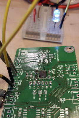
Mit dem Ergebnis bin ich aber sehr zufrieden. Das System kann durch Ziehen von *HVEN nach Masse aktiviert werden, wodurch die LED aufleuchtet. Die Tests auf Unterspannung/Kurzschluss verliefen sehr gut - der Akku ist jetzt geschützt.
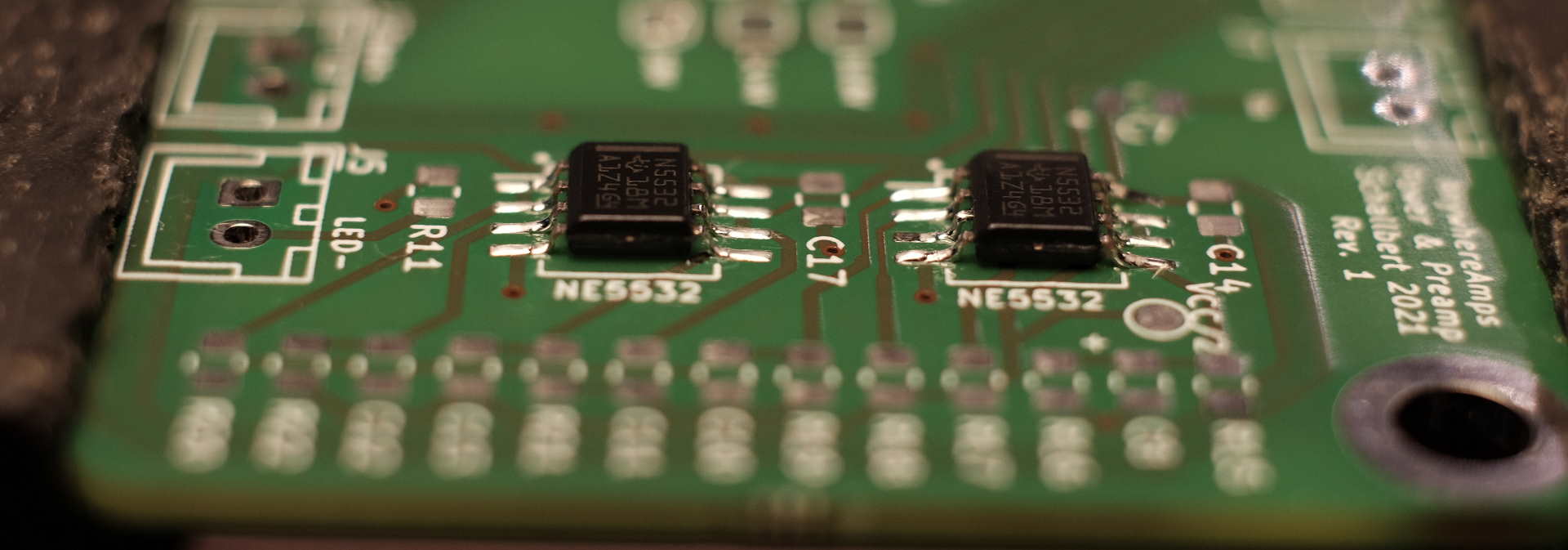
Auch die Vorverstärkersektion war leicht zu löten. Nur die gepolten Kondensatoren erwiesen sich als so groß, dass sie einen großen Teil des Lötpads verdeckten - das ist ein Problem, weil das Lötzinn nicht sowohl Kondensator als auch Pad verbinden wollte, sondern nur an einem der beiden Kontakte hängen blieb. Ich half schließlich mit einem winzigen Stück Brückendraht nach.
Der 9V-Schaltregler-Teil - nun ja… Ich habe es überhaupt nicht geschafft, ihn von Hand zu löten. Quadruple Flat Packs ohne Pins (QFN) sind schon schwer genug zu löten. Aber dieses Teil hier hat auch noch ein freiliegendes Pad auf der Unterseite und ich musste viel Massefläche vorhalten, um die Hitze von diesem Bauteil weg zu bekommen. Also konnte ich nicht einmal die Temperatur für den Lötvorgang hoch genug bekommen. Also habe ich mir eine Heißluftstation geliehen, und nach einigen ängstlichen Versuchen und dem Ertränken der Komponenten in Flussmittel habe ich es schließlich geschafft.
 Mit einem Makro-Objektiv auf meiner Kamera habe ich die Lötstellen dann geprüft.
Funktionstest
Ich habe einen Tiefpass und einen Hochpass in das Design eingebaut, um 2-Wege-Lautsprechersysteme zu unterstützen. Um die drei Vorverstärkerausgänge (Fullrange, Tiefpass, Hochpass) zu testen, habe ich den Vorverstärker direkt an meinen Lautsprecher angeschlossen. Das ist keine gute Idee, denn die Impedanz des Lautsprechers ist viel niedriger als die des OP-Verstärkers, so dass die Ausgangsleistung sehr gering ist. Außerdem verbrauchen die unteren Frequenzen die meiste Leistung, so dass der Klang, den man hört, bereits ein “Hochpass” ist und die Lautstärke des Tiefpasses wesentlich geringer ist. Trotzdem funktioniert es, und ich kann die Verstärkung wie vorgesehen einstellen.
Preamp test
Das war alles, mein Design funktioniert! Da das alles quelloffen ist, steht es jedem frei zum Download auf meinem Github Repo zur Verfügung.
Lektionen
Hier sind die Designfehler, die in Revision2 korrigiert werden sollten:
- Alle Komponenten in der gleichen Ausrichtung platziert werden (z.B. horizontal)
- “Thermische Entlastungen” (kurze Abschnitte, an denen die Leiterplan einen geringeren Querschnitt aufweist) sollten häufiger verwendet werden, um Lötprobleme aufgrund von zu starker Wärmeleitung zu vermeiden.
- Freiliegende Pads: Beim Handlöten müssen die entsprechenden Lötpads zu den Seiten des ICs hin erweitert werden, um die Wärmeleitung des Lots zu verbessern
- QFN-Fußabdrücke sind beim Handlöten falls möglich zu vermeiden. Sie sind lästig.
- Wenn möglich, keine Bauteile mit “exposed pad” oder “power pad” verwenden. Eine Heißluftstation könnte ansonsten unumgänglich werden.
- Schön viel Platz zwischen den Bauteilpads lassen, vor allem bei horizontaler Anordnung.
- Da SMD-Kondensatoren mehr Höhe haben, sollten Sie größere Lötpads vorsehen.