Einschaltstrom ermitteln
Vorbereiten des Multimeters / Oszilloskops

Für diesen Artikel habe ich mir ein Multimeter zur Messung von “Power Quality” direkt vom Hersteller GMC Instruments leihen können. Da dort ein Datenlogger verbaut ist, kann ich die Messungen aufnehmen und später aufbereiten.
Metrahit Energy
Dieses Multimeter ist eher im Profi-Segment angesiedelt. Sowohl der Reichtum an Funktionen als auch sein Preis deuten für mich klar darauf hin. Zusätzlich zum Datenlogger und den üblichen Funktionen eines Multimeters kann es Leistung- und Energie messen bzw. berechnen, harmonische Signalverzerrungen erkennen und nebenbei auch PT100-Temperatursensoren auswerten.
Software setup
So richtet man die Auswertesoftware ein:
- Software MetraWin herunterladen und installieren, um die vom Multimeter erfassten Daten zu übertragen und anzuzeigen.
- Driver-Control “Treiber” herunterladen und installieren. Diese Software dient dazu, die Kommunikation zwischen USB und dem im Lieferumfang des Multimeters befindlichen Infrarot-Schnittstellenadapter bereitzustellen.
- In der MetraWin-Software
METRAHit Starline Seriesauswählen (übrigens ist mir unklar, warum der Name der Serie weder auf dem Gerät noch auf der Website erscheint)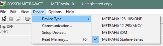
- Nun wird der Infrarot-Adapter am PC angeschlossen. Der IR-Adapter sollte im Gerätemanager mit einer “COM”-Anschluss-ID angezeigt werden (
Windows-Taste–>Gerätin die Suche eingeben undGerätemanagerauswählen –> nach unten zuAnschlüsse (COM & LPT)scrollen, aufklappen). Diese Nummer dann in MetraWinsGerät --> Kommunikation... --> SEL-COMangeben - fertig.
Einrichtung des Multimeters für die Aufzeichnung des Einschaltstroms
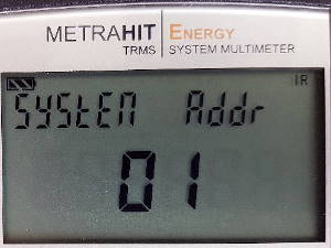 In den Einstellungen dieses Multimeters ist darauf zu achten, dass die Adresse auf einen anderen Wert als
 00eingestellt ist (Setup --> Set --> System --> Addr), da die Infrarot-Kommunikation das Gerät mit einem ungültigen Wert hier nicht erkennt (ich habe dies erlebt und brauchte einige Zeit, um herauszufinden, dass nicht die IR-Adapter-Erkennung fehlerhaft ist, sondern die Einstellungen des Multimeters). Hintergrund ist, dass die Software über die Adressierung bis zu 15 Geräte gleichzeitig unterstützt. Warum00dabei ungültig ist, das wissen wahrscheinlich nur die Entwickler der Software.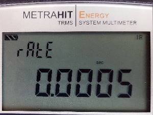 Stellen Sie die Abtastzeit auf den niedrigsten Wert für eine gute Impulsverfolgung ein:
 Measure --> Save --> rateund wählen0.0005secauswählen, was bedeutet, dass der Logger Messungen mit2000HzAbtastrate durchführt. Dies ist der niedrigste Wert, den man erreichen kann, und diese Werte beeinträchtigen bereits die Verfügbarkeit des Aufzeichnungskanals, z.B. für Energiemessungen, aufgrund der begrenzten Pufferfähigkeit des Geräts.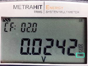 Wählen Sie nun den Wert aus, den Sie messen wollen (bei mir ist es
 DCStrom inAmpère), und passen über dieMAN/AUTOTaste den Wertebereich im manuellen Betrieb so an, dass die zu erwartende Impulshöhe abgedeckt wird. Kleiner Hinweis: Wenn das Multimeter den ZusatzTRMSoderRMSanzeigt, ist dies für unsere Messung hier eher nicht erwünscht, da in diesem Falle eventuelle Spitzenwerte geglättet werden.
Um den Einschaltstrom meines Verstärkers zu bestimmen, verwende ich den Messbereich >10A. So habe ich zwar eine für den Normalbetrieb geringe Genauigkeit, kann allerdings die Stromspitze gut abbilden.
Alternative Messgeräte
Oszilloskope sind Multimetern bei der Zeitauflösung weit überlegen, benötigen aber weitere Hilfsmittel um Ströme exakt erfassen zu können.
Dennoch sind sie hier mit einfachen Hilfsmitteln verwendbar: Einen Widerstand mit niedrigem Wert (z.B. 0.1 Ohm) und geringer Toleranz in Reihe mit dem Prüfling schalten und den Spannungsabfall am Widerstand per Oszilloskop bestimmen. Bei einer Auflösung von 1V/div läge dann die Umrechnung für den Einschaltstrom bei 10A/division.
Ein günstiges Multimeter hingegen mit “Data Max Hold” Funktion wird für diesen Anwendungsfall wahrscheinlich aber nicht funktionieren, da die Messintervalle für die zu messenden, sich schnell aufladenden Kondensatoren schlicht zu lang sind.
Der Prüfling
Die zu untersuchende Schaltung ist eine Endstufe mit 30W Dauerleistung AA-AB32996, produziert von “sure electronics”. Er basiert auf dem integrierten Class-D-Verstärkerbaustein TPA3110.
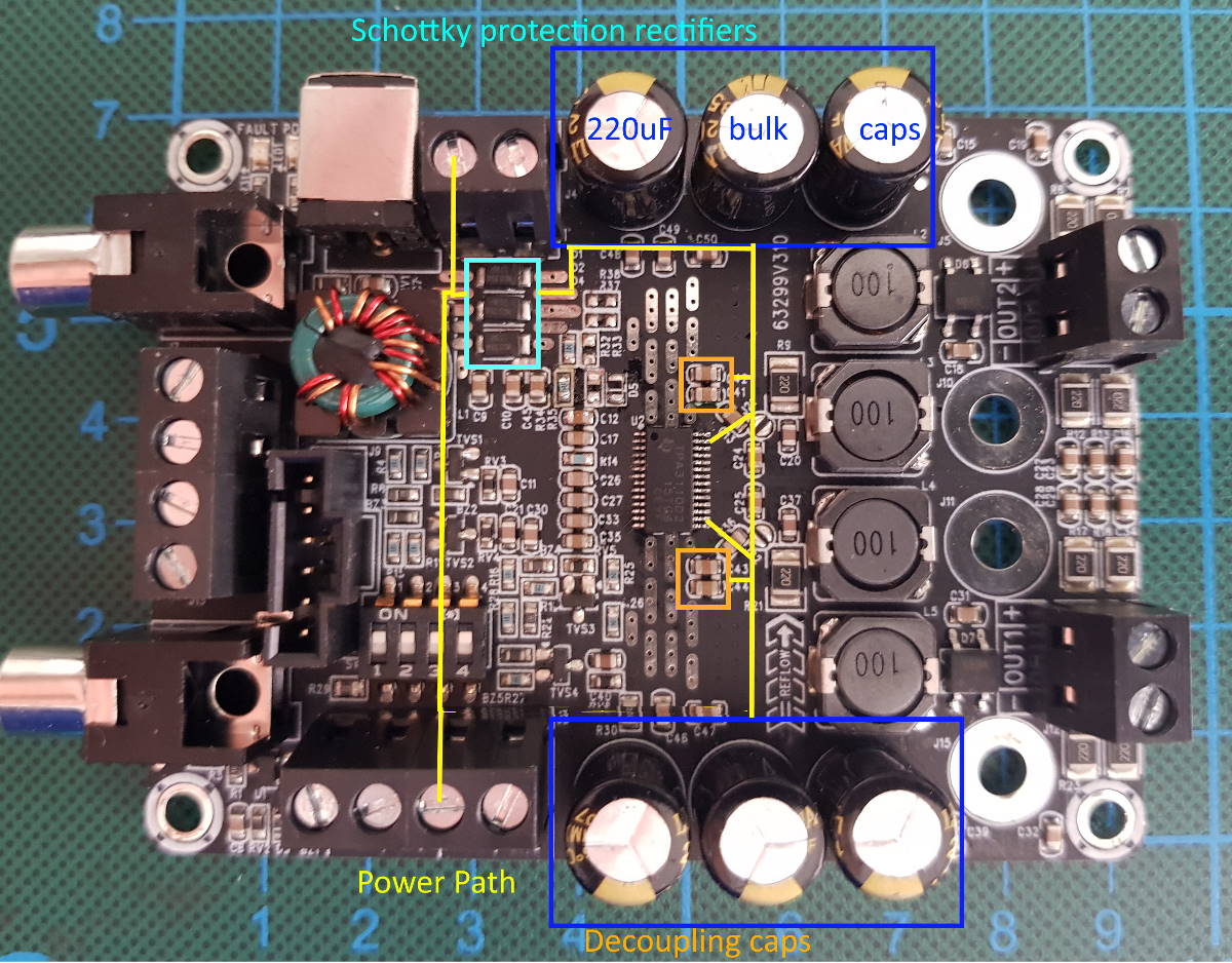
Die Energieversorgung besitzt einen Verpolschutz (drei parallel geschaltete Schottkydioden) und bindet sechs Pufferkondensatoren mit einer Kapazität von je 220uF ein. Zusätzlich befinden sich nahe der Versorgungspins des IC zwei weitere Entstörkondensatoren.
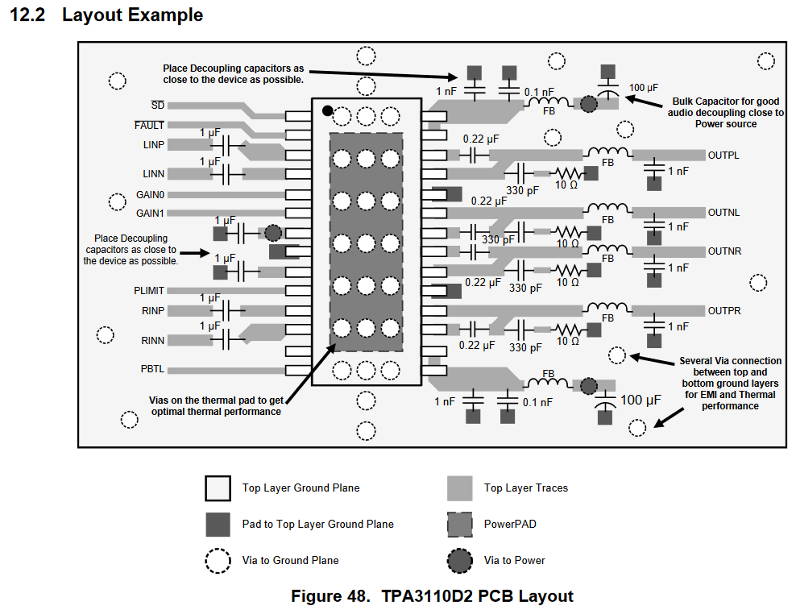
Zum Vergleich: Das Referenzlayout des IC-Herstellers sieht der oben beschriebenen Lösung recht ähnlich. Hier werden zusätzlich FB (Ferritkerne) verwendet, um die Ströme auf der Eingangsseite zu glätten. Dafür wird weniger Pufferkapatizät vorgesehen.
Darüber hinaus verwendet das Referenzdesign einfache Ferritkerne anstatt hochwertigerer Filterspulen am Verstärkerausgang.
Motivation: Ausfall eines Prototypen bei Verwendung von USB-C PD
Für einen meiner Prototypen hatte ich vorher ein USB-C Power Delivery Entwicklungsboard - erklärt in diesem Beitrag - verwendet. Leider musste ich feststellen, dass dieser nach nur ein paar Einschaltzyklen in Rauch aufging - wahrscheinlich verursacht durch einen hohen Einschaltstrom, für den der IC nicht ausgelegt ist.
Daher wollte ich genau wissen, wie hoch die Stromspitzen sind und mit welcher Komponente ich den Einschaltstrom so in den Griff bekomme, dass hierdurch verursachte Schäden an elektronischen Bauteilen ausgeschlossen werden können.
Durchführung der Messung
Ich verbinde den Messpfad für Strom des Multimeters mit dem Minuspol des Verstärkers und die Masse des Multimeters mit dem Minuspol des Netzteils. Die Messspitze für Spannung verbinde ich mit dem Pluspol des Verstärkers, und letzteren wiederum schließe ich über einen Schalter am Netzteil an.
Um die Messung zu beginnen, wähle ich beim Multimeter SET --> Store --> Start --> Store und lege den Schalter an der Spannungsversorgung um. Nach ein paar Sekunden beende ich die Messung mit der Taste Stop.
Da ich zu beginn die höchstmögliche Datenrate eingestellt hatte, musste ich die Daten hernach manuell an den Computer übermitteln und konnte nicht die Liveübertragung wählen. Hierfür wählt man in der Software folgende Einstellung aus: Read Memory --> Get Memory Info --> Move Memory Data to File --> save --> Open Memory Data File --> Display Data from File. Mir ist dabei nicht ganz klar, warum an der Stelle so viele Schritte erforderlich sind - ich hätte hierfür nur einen Knopfdruck erwartet.
Das Dateiformat Measurement Data File hat einen großen Vorteil gegenüber dem ebenfalls möglichen Memory Data File: Es enthält Metadaten wie Messdatenauswahl für die Ansicht, Labels und Details zur Darstellung wie Einheiten etc. Ohne großen Aufwand lassen sich Auswertungen erstellen und beispielsweise im PDF-Dateiformat exportieren.
Visualisierung des Einschaltstroms
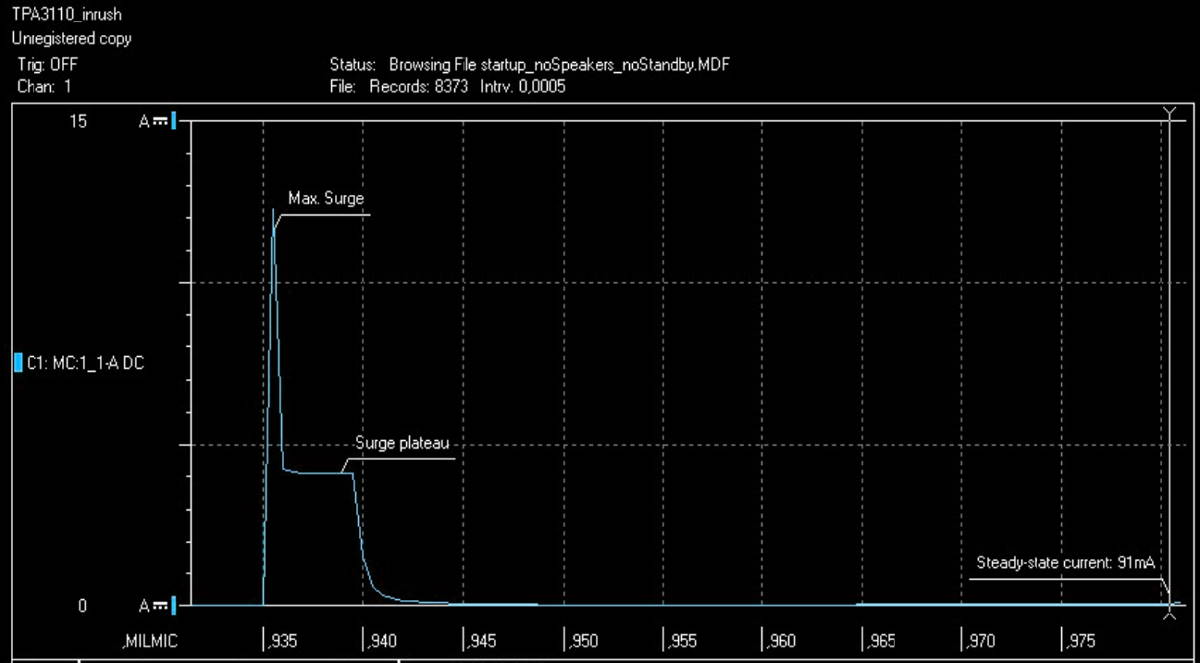
Der ganze Spuk dauert nur ~10ms, also 20 samples. Nach einem hohen Strompuls von >12A zeigt sich ein Plateau bei rund 4A bis sich die Kondensatoren aufgeladen haben. Danach geht der Strom zurück, bis er dem Leerlaufstrom des Verstärkers entspricht.
Der Spitzenwert liegt allerdings nur für einen Datenpunkt vor - daher kann ich nicht sagen, ob es sich um einen Messfehler / Ausreißer oder ein tatsächliches Ereignis handelt. Ein paar Annahmen zur Ursache:
- Es wurden schaltungsweit Entkopplungskondensatoren mit sehr geringem ESR (Serienwiderstand) verwendet
- Verlassen des Messbereichs des Multimeters
- Limiter des Labornetzteils begrenzt den Strom auf Niveau des Plateaus (war auf
5Akonfiguriert, passt also nicht recht zusammen)
Spannungsverlauf an den Versorgungspins des Verstärkers
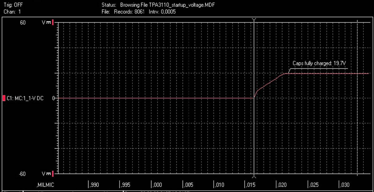
Die Spannungsmessung zeigt einen sprunghaften Anstieg beim ersten Messwert nach Einschalten des Verstärkers, gefolgt von einem fast linearen Anstieg bis die Quellspannung nach etwa ~6ms erreicht wird.
Diese Werte passen zeitlich prima mit den Strommessungen zusammen und bestätigen sowohl Impuls- als auch Plateauwerte.
Wiederholung & Ergebnis
Ich wiederholte die Messung mit unterschiedlichen Randbedingungen: Lautsprecher angeschlossen/ nicht verbunden, Verstärker in Standby/ Leerlauf usw. aber die Messergebnisse waren stets ähnlich. Somit wird die Verstärkerschaltung im Moment des Einschalten nicht durch seine Konfiguration oder Peripherie beeinflusst.
Die Werte sind also bedingt durch den Versorgungspfad und seine Schutzmaßnahmen, Energiespeicher und seine Entkopplungsschaltung.
Nachteile der Messung mittels Multimeter sind geringe Datenrate (10-100kHz wären besser gewesen), keine Möglichkeit, die Messwerte live abzulesen, und langen Datentransferzeiten zum PC, geschuldet durch die Kommunikation per Infrarot. Andererseits kann ich das Multimeter jetzt schnell mal als “offline Datenlogger” auch über längere Zeit verwenden, ohne einen Computer zur Konfiguration dabei haben zu müssen. Optimal für die Anwendung im Feld.
Für den Verstärker werde ich mit diesen Erkenntnissen jetzt eine Schutzschaltung entwickeln, ähnlich wie in diesem Beitrag diskutiert, und so in Zukunft Probleme mit USB-PD ICs vermeiden.