Einschaltstrombegrenzer - Teil1
Elektronikwissen: Einschaltstrombegrenzer
Einschaltstrombegrenzer in Aktion. Details hier
Was ist das?
Ein Einschaltstrom ist der Stromstoß, der direkt nach dem Einschalten durch einen Stromkreis fließt, bis der Stromkreis seinen stabilen Zustand erreicht hat. Hohe Einschaltströme sind oft unerwünscht, da sie Schaltungsteile überlasten und deren Lebensdauer verkürzen können, elektromagnetische Störungen verursachen und einen kurzzeitigen Spannungsabfall bewirken, der zu ständigen Neustarts eines gesteuerten Geräts wie hier beschrieben oder zu anderem unerwünschten Verhalten führen kann.
Beispiel

Glühlampe: Die rosa Linie ist die Ausgangsspannung des Netzteils, die gelbe Linie zeigt den Strom. Man kann erkennen, dass das Netzteil die Ausgangsspannung verringert, um die Stromaufnahme während des Starts zu reduzieren. Nach etwa 100ms stabilisiert sich die Spannung, da der Stromfluss durch die Lampe immer noch ein wenig abnimmt, während der Glühfaden langsam seine Temperatur erreicht.
Hintergrund
Der Glühfaden des Leutmittels wirkt wie ein Widerstand mit positivem Temperaturkoeffizienten (PTC): Bei Raumtemperatur hat er einen sehr niedrigen Widerstand, bei seiner normalen Betriebstemperatur von ~3300K einen viel höheren.
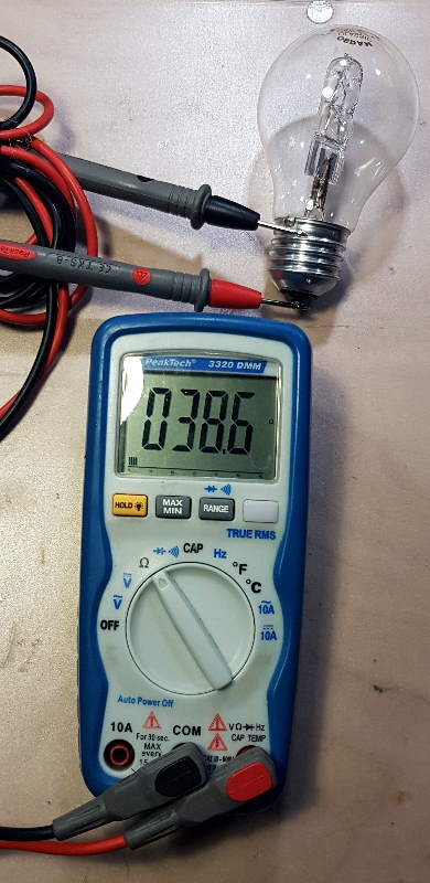
Ein kleines Experiment beweist dies:
Nehme ich eine “116W”-Halogenglühbirne, so beträgt ihr Widerstand im “eingeschwungenen Zustand” bei 230V etwa \(R_{steady} = \frac{U^2}{P} = 456{Ohm}\).
Wenn ich den Widerstand der Lampe im kalten Zustand mit einem Multimeter messe, liegt der Wert bei \(R_{off} = 38.6{Ohm}\).
Während durch die Glühlampe im eingeschalteten Zustand ein Strom von \(I_{steady} = 0.5A\) fließt, liegt ihr Einschaltstrom bei etwa \(I_{inrush} = 6A\) - also zwölf mal so hoch!
Einschaltstrombegrenzer-Schaltungen
Einschaltstrombegrenzer werden häufig in Geräten mit großen induktiven oder kapazitiven Lasten eingesetzt. Beispiele (Link zu Texas Instruments) sind Transformatoren, Motoren (induktiv), Leistungsverstärker, Schaltnetzteile (kapazitiv) usw.
Es gibt verschiedene Arten von Einschaltstrombegrenzern (TI application note) mit unterschiedlicher Komplexität.
Widerstand mit negativem Temperaturkoeffizient (NTC) / Heißleiter / Thermistor
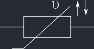 Ein Einschaltstrombegrenzer als NTC-Widerstand in Reihe zur Last ist die einfachste Schaltung in dieser Aufzählung. Sie besteht aus nur einem zusätzlichen Bauteil. Das Verhalten des NTC-Widerstands gegenüber der Temperatur ist dem des obigen Glühbirnenbeispiels entgegengesetzt: Sein Widerstand nimmt mit steigender Temperatur ab, so dass mehr Strom durch den Stromkreis fließen kann.
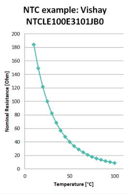 Bei den meisten NTCs verhält sich der Widerstand logarithmisch zur Temperatur, er sinkt also sehr stark bei zunehmender Temperatur. So kann er Einschaltstrompulse sehr effektiv unterdrücken. Nachteilig ist der Eigenenergiebedarf, der den Widerstand auf Betriebstemperatur hält.
Diese Schaltung wird dort verwendet, wo geringe Kosten wichtig sind, das System einfach gehalten werden soll und der zusätzliche Energieverbrauch kein Problem darstellt.
Bei den meisten NTCs verhält sich der Widerstand logarithmisch zur Temperatur, er sinkt also sehr stark bei zunehmender Temperatur. So kann er Einschaltstrompulse sehr effektiv unterdrücken. Nachteilig ist der Eigenenergiebedarf, der den Widerstand auf Betriebstemperatur hält.
Diese Schaltung wird dort verwendet, wo geringe Kosten wichtig sind, das System einfach gehalten werden soll und der zusätzliche Energieverbrauch kein Problem darstellt.
Widerstand mit Bypass-Relais
Diese Schaltung vermeidet die Nachteile eines zusätzlichen Serienwiderstands zur Last durch Hinzufügen eines Leistungswiderstands und eines Relais. Sie wird typischerweise in Gleichstromversorgungen mit hoher Leistung oder empfindlichen Geräten wie Verstärkern verwendet. Der Relaiskontakt ist im unbestromten Zustand offen und parallel zum Leistungswiderstand verdrahtet, der je nach Last einen Wert von typischerweise “1…22 Ohm” hat. Dahinter wird die Last angeschlossen, die den Einschaltstrom verursacht. Für dieses Beispiel nehme ich die Glühbirne eines Autos als Last. Beim Einschalten des Geräts begrenzt der Widerstand den Stromkreis und die Spannung auf der Lastseite steigt allmählich an. Sobald die Spannung an der Basis des NPN-“BC337”-Transistors hoch genug ist, schaltet er sich ein und lässt Strom durch die Relaisspule fließen, die dann den Leistungswiderstand kurzschließt, so dass die Last ihren Nennstrom ziehen kann.
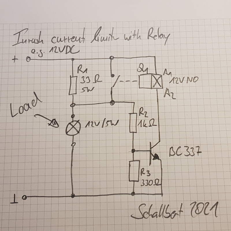
Die Werte von R2, R3 hängen von der Spannung hinter R1 ab, wenn sich die Schaltung bei ausgeschaltetem Relais im eingeschwungenen Zustand befindet. Des Weiteren ist die Charakteristik des Transistors und der Betriebsstrom der Relaisspule zu berücksichtigen. In meinem Beispiel wählte ich R2 = 1kOhm, da der Transistor ~40mA für den Betrieb des Relais durchlassen muss. Diesen Wert habe ich dem Datenblatt des BC337, Parameter Stromverstärkung, entnommen. Da ich das Relais nicht zu früh schalten lassen wollte, habe ich R3 hinzugefügt. Je höher sein Widerstand, desto früher wird das Relais aktiv. Ein zu geringer Widerstand hingegen reduziert die Basisspannung des BC337 so weit, dass er das Relais nicht mehr treiben kann - hier muss ein wenig experimentiert werden.
In diesem Anwendungsbeispiel für den “Soft Start” eines Ringtrafos (Elektronik-Kompendium) kommt eine ähnliche Schaltung zum Einsatz.
Und so verhält sich der Schaltkreis in der Realität:
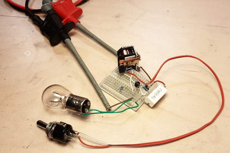 Ich habe mir die Freiheit genommen, einen Schalter hinzuzufügen, damit die Steuerung der Stromversorgung für mich bequemer wird. Das Relais ist mit einer Freilaufdiode ausgestattet, um den Transistor vor negativen Spannungsspitzen zu schützen.
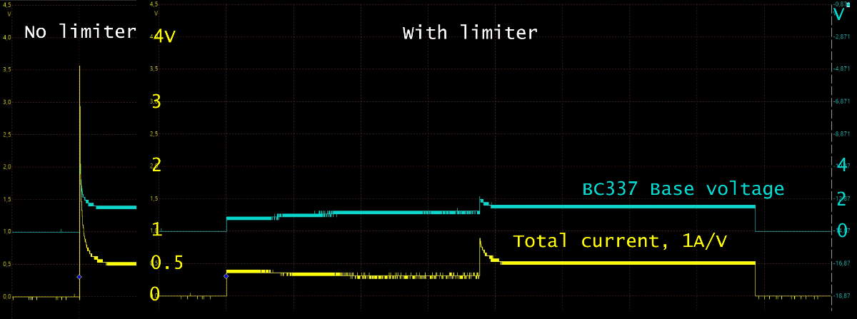
Das Problem des Einschaltstroms ist tatsächlich gelöst. Der Vergleich (gelbe Linie) zeigt einen ungeregelten Einschaltstrom von 3.5A, während der Begrenzer ihn auf 0.8A reduziert, was nur knapp über dem Nennstrom liegt. Ein Leistungswiderstand mit kleinerem Wert hätte diesen Strom noch weiter reduziert.
Die grüne Linie zeigt die Basisspannung des BC337 an. Man erkennt, dass sie langsam ansteigt (die Genauigkeit des Oszilloskops ist bei 40VPP nicht die beste) und das Relais einschaltet, wenn sich der Stromfluss (gelbe Linie) stabilisiert hat.
Sanftanlauf / konfigurierbare Strombegrenzung
Es gibt spezielle ICs, die den Sanftanlauf eines Systems unterstützen, je nach
- Leistungsbedarf
- Hochlaufzeit
- Beschränkungen der Anstiegsgeschwindigkeit
- Maximalstrom
Darüber hinaus gibt es verschiedene Arten von Einschaltstrombegrenzern, die je nach Anwendung ausgewählt werden können:
- Zeitgesteuert: Das System wird nach einer bestimmten Zeit vollständig eingeschaltet (einfach, aber dumm)
- Spannungsgesteuert: Das System wird oberhalb eines Spannungsauslösepegels vollständig eingeschaltet (immer noch einfach, mittlere Kosten)
- Stromgesteuert: Begrenzt den Systemstrom oder schaltet das System auf der Grundlage eines Stromauslösepegels vollständig ein (wahrscheinlich teurer)
Hinsichtlich der Anforderungen des Systems muss dann ein passender IC gewählt werden. Typische Namen sind hier
Power Supervisors,IC soft starter,Supervisor & Reset ICoder ähnlich. Sie können intern sogar mit Leistungstransistoren ausgestattet sein und selbsttätig schalten, wie z.B. MAX17562 (Maxim Integrated) für meine Evolution von AnywhereAmps.
Weiterlesen: Einschaltstrombegrenzer - Teil2