Einschaltstrombegrenzer Teil2
Inhalt
In diesem Artikel konzentriere ich mich auf zwei Möglichkeiten, eine Halbleiter-Einschaltstrombegrenzerschaltung zu erstellen: Die eine kopiert den Relais-Ansatz aus Elektronikwissen: Einschaltstrombegrenzer, wobei lediglich das Relais durch einen p-Kanal-MOSFET ersetzt und eine besser definierte Zeitverzögerung hinzugefügt wird. Zum anderen stelle ich einen “linearen” Ansatz vor, bei dem die Stromversorgung schrittweise durch einen PNP-Leistungstransistor eingeschaltet wird.
Motivation: Einschaltstrombegrenzer für USB-PD
Da meine Experimente mit USB-PD für AnywhereAmps vorerst fehlgeschlagen sind, muss ich eine Schaltung erstellen, die den Einschaltstrom in meinem Verstärker begrenzt, bevor ich es erneut versuche.
Schaltungen erläutert
Die beiden Schaltungen sind sich sehr ähnlich. Sie unterscheiden sich eigentlich nur in zwei Komponenten des Leistungsteils. Im Allgemeinen wird die Verzögerungszeit durch eine Vergrößerung des Kondensators C4 oder eine Vergrößerung des Ladewiderstands R9 verlängert.
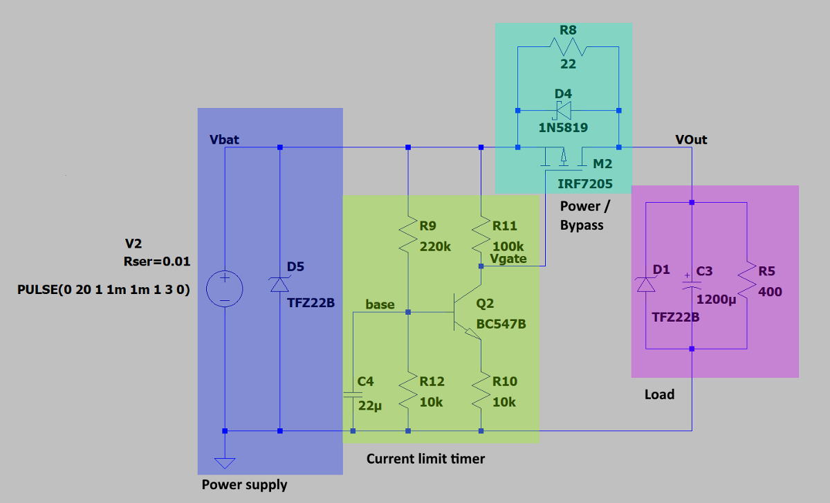
Eingangsbereich (blau)
Der Eingangsteil verfügt über eine TVS-Diode, um Verpolung oder Überspannung zu vermeiden.
Verzögerungsabschnitt (gelb)
Nach dem Einschalten wird C4 über R9 allmählich aufgeladen. Wenn die Schwellenspannung des NPN-Bipolartransistors Q2 erreicht ist, wird die Spannung hinter R11 langsam reduziert, was wiederum M2, den Leistungspfad dieser Schaltung, aktiviert. R12 wurde hinzugefügt, um einen stabilen Arbeitspunkt für Q2 zu schaffen.
Leistungsteil (grün)
Die lineare Variante hat einen PNP-Leistungstransistor Q1 im Hauptstrompfad (Bild unten). Er wird über Q2 aktiviert, und der Strom, den er liefern kann, wird über R10 gesteuert, der in diesem Fall einen relativ niedrigen Wert hat um hohe Emitter-Kollektor-Ströme zu ermöglichen.
Während die schaltende Variante einen Strombegrenzungswiderstand R8 verwendet, der durch den p-Kanal-Mosfet M2 kurzgeschlossen wird, erfordert seine spannungsgesteuerte Natur keine besondere Sorgfalt bei der Auswahl von R10. Man sollte nur darauf achten, dass seine (negative) Gate-Schwellenspannung sicher eingehalten wird.
Simulierte Last (violett)
Meine Last ist die Endstufenschaltung. Um den Ruhezustand und das Einschaltverhalten zu simulieren, habe ich einen 400Ohm-Widerstand R5 und einen gepolten 1200uF-Kondensator C3 gewählt. Die TVS-Diode schützt vor Überspannung und Rückströmen. Ich habe die Simulationen mit Kondensatorwerten von bis zu 10000uF und Lastwiderständen bis herunter auf 40Ohm ausprobiert, alle mit ähnlichen und guten Ergebnissen.
Schaltungsvergleich
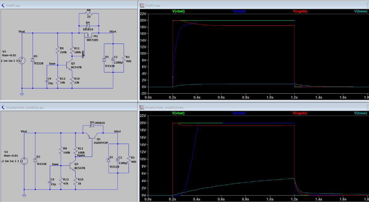 Die dunkelblaue Linie im Diagramm ist wichtig: Sie beschreibt die Ausgangsspannung des Systems im Zeitverlauf. Beide Schaltungen sind so abgestimmt, dass sie die Ziel-Ausgangsspannung nach 0,2 Sekunden erreichen. Dennoch unterscheiden sich die Kurven ziemlich stark, was die unterschiedliche Natur der beiden Ansätze widerspiegelt.
P-CH MOSFET Ansatz
- Aufgrund des Schaltvorgangs ist die Einschaltstrombegrenzung zwar wirksam, aber nicht ganz gleichmäßig
- die Leistungsverluste sind bei dieser Variante sehr gering, da sowohl der auslösende NPN-Transistor als auch der Leistungs-MOSFET für sich genommen nicht viel Strom verbrauchen.
- breiter Einsatzbereich für angeschlossene Geräte, der nur durch den maximalen Dauerstrom des MOSFETs begrenzt wird.
PNP-Leistungstransistor-Ansatz
- sehr ruhiger Betrieb, die Einschaltzeit kann aufgrund des großen ohmschen Bereichs des PNP sehr gut gesteuert werden
- höhere Leistungsverluste im eingeschalteten Zustand aufgrund des hohen Basisstroms durch
R10. - Nicht sehr vielseitig, da hohe Lastströme einen beträchtlichen Spannungsabfall über den Emitter-Kollektor-Pfad von
Q1erzeugen.
Weitere Verbesserungen
Um die Vielseitigkeit dieser Schaltung zu behalten und gleichzeitig eine glatte Spannungskurve zu erreichen, könnte man einen Operationsverstärker verwenden, um den Laststrom zu überwachen und ihn bei Bedarf auf die zulässigen Werte herunterzuregeln. Der Leistungs-MOSFET könnte beibehalten werden, während der Nachteil des engem ohmschen Betriebsbereichs verschwinden würde. Der Preis dafür wäre zusätzliche Komplexität, wie sie in diesem Stackexchange-Beitrag beschrieben wird.