Spirograph
The spirograph
Spirographs are mathematical toys. With their help it is easy to draw repetitive, curved shapes. The simplest version is made up of a cogwheel that runs on the inside of a static ring gear. The running wheel has a couple of holes to take the tip of a pen. The holes are located out of center of that cogwheel so, when rotating the wheel inside the hollow one, it will create parabolic shapes.
The number of rotations needed to draw a closed shape depends on the relation of tooth count between the two wheels.
Version 0
Our initial design was created together with the guys from CADasCAM in the workshop. It is a 14:9 tooth combination, so the lowest common multiple (aka LCM) is 126 which would create tight drawings with 126 / 9 = 14 corners. We had it manufactured in Aluminium and discussed about a good milling strategy using the CAM part of their software.
Milling Spirograph_V0 on an overclocked CompactLine CNC
The parts turned out good and the wheels would allow cog to cog placement but unfortunately, it wouldn’t turn because the inner wheel’s next cog wouldn’t hit the flank but instead the ring gear tooth’s head.
Version 1
When the workshop was over, I took the design home and tried to improve. I shortened the tooth heads of the outer wheel to fix the previous issue and had some rounds added so the wheels wouldn’t feel edgy.
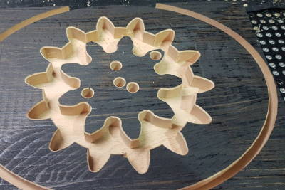 I had the design manufactured in 18mm Beech glued wood. I introduced two-sided milling here because chamfering by hand turned out to be a bit tedious at these more complex shapes. For that, I did not cut right through the material but left a 1mm “onion skin” at the bottom which would hold everything in place.
When I finally had the edges of the lower side chamfered, the bit would pierce the onion skin and practically cut out the workpieces so that I’d just have to snatch them off the machine bed. I just had to sand down the burrs which took less than five minutes of manual rework.
 But it still wouldn’t fit. This time, because the flanks of the inner wheel were too wide. As a consequence, they would not allow full engage depth which in turn makes the next tooth of the inner wheel hit the tooth’s head of the ring gear.
Version 2
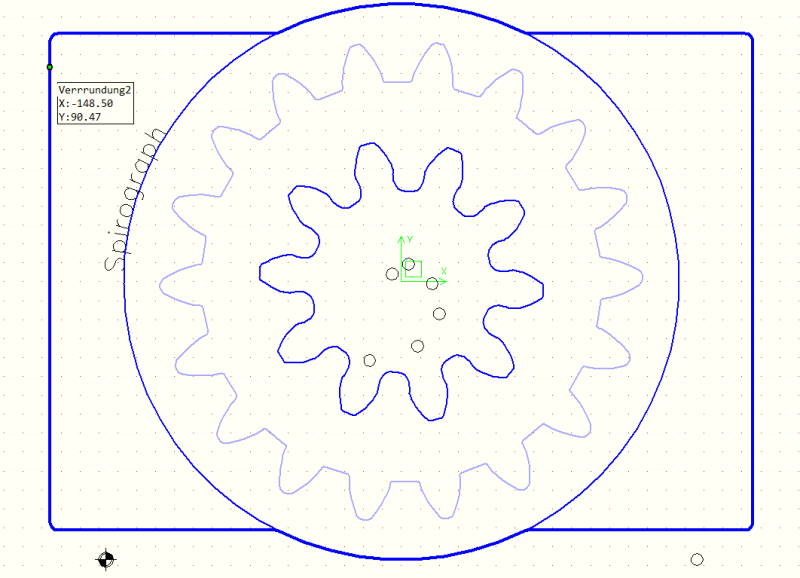
I figured out that in Version_1, the inner wheel had a positive tooth profile shift value while the ring wheel was left at zero. This couldn’t work at all so I fixed it. I also reworked both wheel’s concave radiuses so a 6mm endmill would be able to properly carve all details. Finally, I added some play for the teeth flanks and allowed for more room in the teeth’s troughs for better tooth meshing.
 To give more room to the inner wheel, I mutated the gear combination to 16/7 that will draw
 112 / 7 = 16 corners (even tighter drawing).
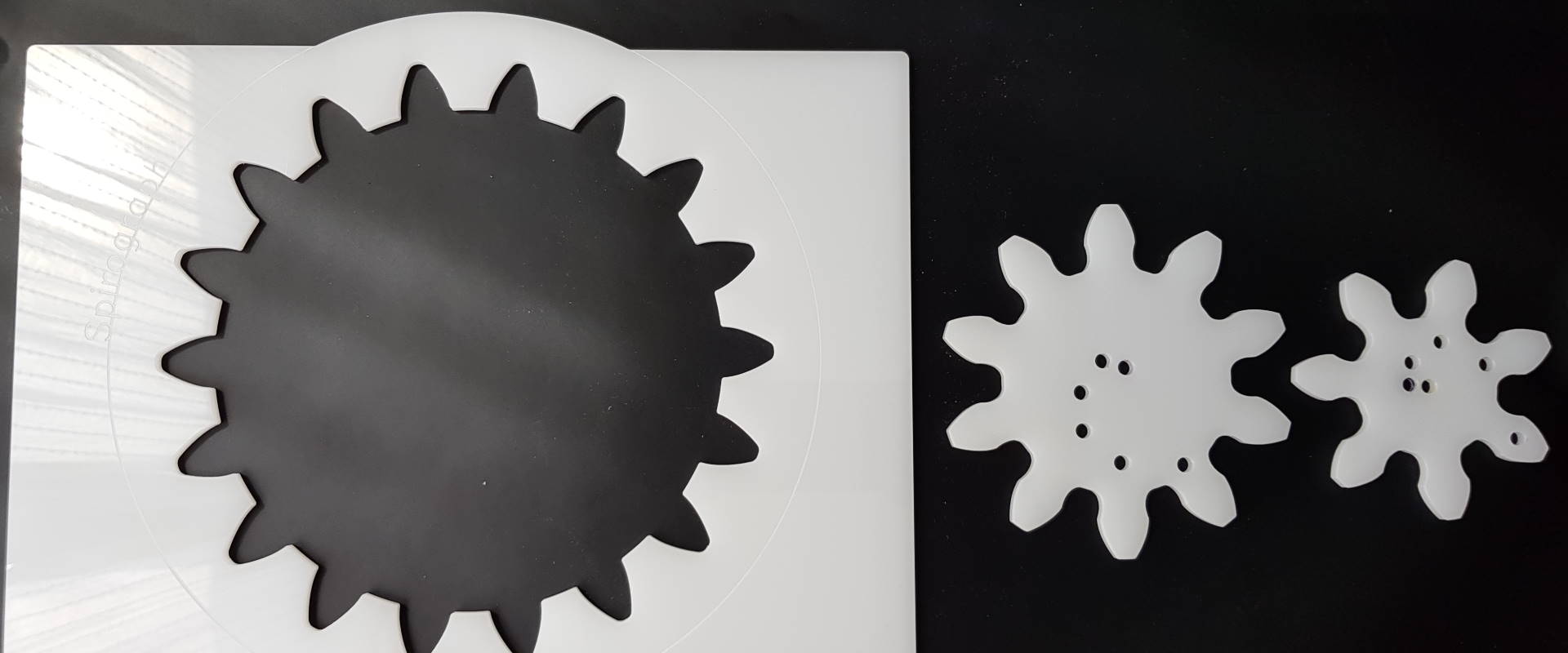
This time I had it manufactured in 5mm extruded Acrylic (PMMA), opaque white. I went with a similar two-sided milling strategy as discussed above, but I added a finishing run for superior quality of cut. I used the following parameters:
| Cutter, Material: PMMA (Acrylic) | Work type | Tooth | Dia [mm] | Speed [RPM] | Feed [mm/min] | Z+ [mm] | XY+ [mm] |
|---|---|---|---|---|---|---|---|
| carbide hawk beak upcut FSECO1 | Roughing | 1 | 4 | 24000 | 3000 | 8 | 3.6 |
| carbide hawk beak upcut FSAC | Finishing | 1 | 4 | 26000 | 3000 | 8 | 0.2 |
| carbide taper 90° FEF | Chamfers | 3 | 10 | 15000 | 5000 | 3 | 3 |
And it worked flawlessly 😄, quality of cut was very high and all I did manually was to use a scraper for deburring that took under a minute.
Updated tooth parameters allow smooth meshing
But still there was room to improve:
- Holes right in the teeth don’t make sense because the inner wheel would not want to turn when engaged
5mmholes are a bit too small to home all sorts of crayons- 16 teeth modul10 are not enough to fill a DIN A4 sheet of paper
- The elliptic shape looks nice but is a bit hard to keep in place
That’s why I made one more step in the evolution:
Version 3
I made another slight update over Version_2, this time with an 18/10 pairing (LCM of 90, so 9 corners). I reworked the hole distances in form of a fibonacci spiral to yield more expressive designs. Finally, I updated the outline to match DIN A4 paper size so that the designs now would be centered.
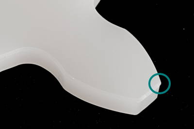 I used the same parameters as in the previous version for manufacturing. See for yourself how good it came out. I wonder if I can get the last 5% out of quality by avoiding burrs altogether. Alone, I wouldn’t knnow how. Looks like the burr is created when the tapered cutter pierces the underside of the material to make the final cutout on my vacuum table.
 Another thing I noticed is that the machine creates chatter marks when accelerating to target speed in
 G01 operations. I guess this is due to the limited frame stiffness. It is noticeable only under a few angles but not palpable.
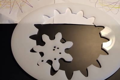
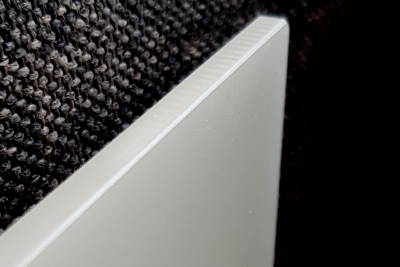
The finished product then looks like this. Due to the chamfers and rounded edges, it feels really smooth. The gears run effortlessly the 18/10 cog combination has so many teeth meshed at all times that even kids aged 5 have no issue to produce perfect shapes (tested it).
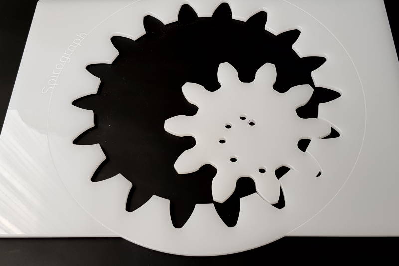
And finally, I’m also happy with how the drawings look. Bold, big enough (15x15cm / 6" by 6"). Lines stand together not too tight. The higher number of holes that the larger inner wheel allows help generating higher diversity figures as well.

I will donate the specimen to a nearby school. Let’s see how they use them.
You want to DIY?
No problem. Download a ZIP package here.
What’s in the package?
- CADasCAM project that allows all sorts of wheel pairing configurations
- Drawing files (
DXF) both for front and rear milling - EstlCAM project files along with my tool database
- CNC operations files (
tap) that fit my machine - A readme (
txt) that defines XY zero and required offsets
Does it cost anything?
No, it’s for free. Note that the License I use makes the package “free software”. Please contact me if you want to utilize anything of the designs in other contexts than home and private usage.
Disclaimer
As usual, the files are available for download free of charge. In turn, I do not take any responsibility or liability for their contents.
WARNING ⚠️
These files provide or allow output of G-code instructions for real machinery that does actually do things in the physical world. There might be code errors or bugs that could potentially lead to machine crashes or even worse. I do not take liability for work accidents, system failures, equipment breakdown, loss of production, flow disturbances, or other negative effects that may be caused through the files I provided.
NOTE ℹ️
It is the machine operator’s responsibility to carefully review G-code and to make sure that it works as intended on the specific machine without causing any harm.