CNC spoilboard
Project stats
- Difficulty: medium 3/5
- Cost: ~60€
- Time: ~6h
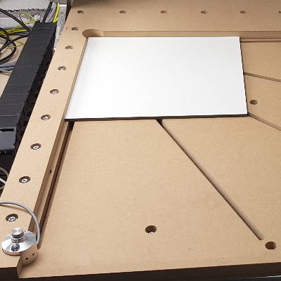 This is how to make a versatile spoilboard for your CNC application. The design uses hammer nut slots in different angles to enable very flexible clamping. It also includes a fence that makes preparing sheet material cuts easy: workpiece zero is at the same spot every time, and clamping against the fence might already suffice so that no load in Z-direction is needed. The fence has two cutouts: One to hold the tool-length sensor, and another one at XY-zero to mitigate tool collisions during rapid positioning.
Simple adjustment for your CNC
The dimensions I took are matching for a Basicline 0607 portal milling machine. But as I’m using a parametric CAD tool, all you need to do is to change dimensions to fit your machine, resolve some drawing quirks and you’re good to go with your own design.
The idea
As indicated above, the spoilboard has to meet the following criteria:
- Mountable on CNC machine’s base frame (hammernuts / M5 fasteners)
- Mount point close to XY-zero
- T-slots for flexible mounting at 0°, 22.5°, 45°, 67.5°, 90°
- Fence, quick-mount onto spoilboard to simplify clamping and improve repeatibility
- Fence to hold tool-length sensor
- Fence to provide a cutout at XY-zero
- Shall be manufacturable on the CNC it’s designed for (multi-job if needed)
Design phase: CAD
I started with a dimensions table in Freecad and a couple of empty-sheet sketches.
Mounting to base frame
 In the spreadsheet, I started by both entering the base frame’s and the CNC travel range’s dimensions, the drive-in nut’s, washer’s, and fastener’s parameters.
I measured the exact positions of the base frame’s t-nuts where I wanted the spoilboard to mount onto and entered them in the spreadsheet.
In the spreadsheet, I started by both entering the base frame’s and the CNC travel range’s dimensions, the drive-in nut’s, washer’s, and fastener’s parameters.
I measured the exact positions of the base frame’s t-nuts where I wanted the spoilboard to mount onto and entered them in the spreadsheet.
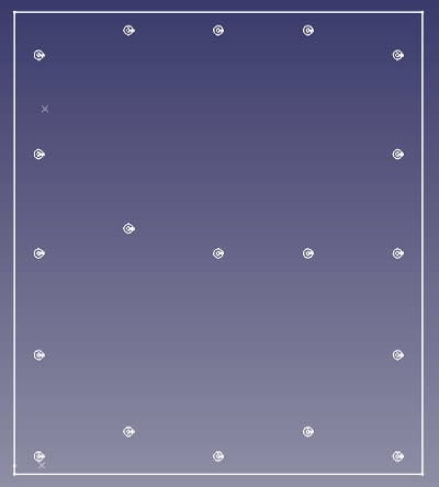
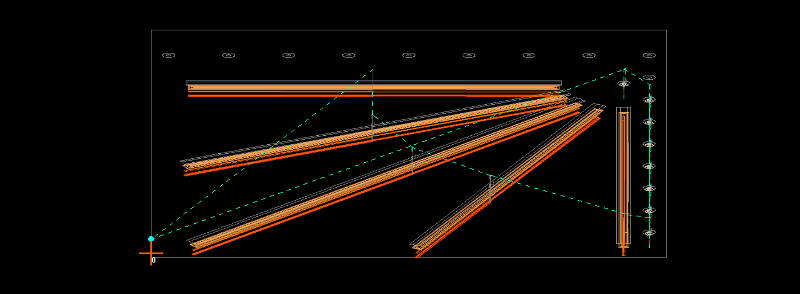
When this was done, I opened the first sketch and drew the spoilboard’s rectangle, fully constraining its dimensions with the data from the spreadsheet. I added construction lines (i.e. lines that wouldn’t show in the final drawing, but help anchor constraints, draw lines, or mark symmetry within a drawing) where the base frame’s T-nut centers are positioned.
I added concentric circles for washer countersinks and through-holes in evenly distributed distances. They will later hold the fasteners and their washers. I didn’t decide on their final position on the Y-axis yet, as the spoilboard’s T-nuts would interfere with some of these mounting points.
The CNC job for this sketch will have to be done on the “top side” of the spoilboard.
T-nut slots and fence mounting points
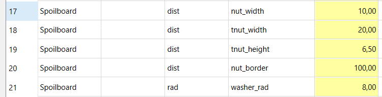
Now it was time to add some data to the spreadsheet again: T-nut slot parameters, angles, border width like so:
 First I had to add construction lines on the spoilboard to mark where the CNC’s travel range. Second, I had to reserve some room for the fence. Only then could I start to draw and position the T-slots which each had different angles and lengths based on the border I wanted to keep for stability reasons.
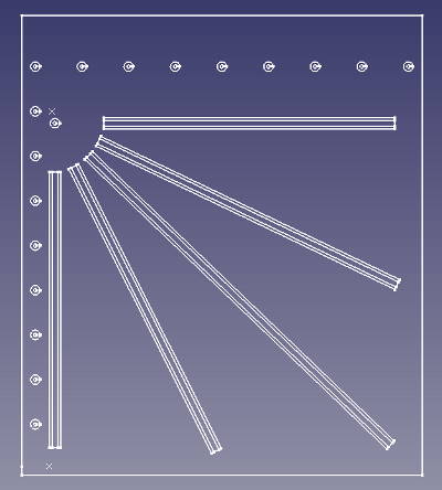 Every T-slot would get a symmetry construction line around which two rectangles reside to mark slot and rebate shoulders.
Then I added countersinks for bolt-in nuts that will later hold the fence on the spoilboard’s margin. In their center, I provide hole-throughs for the fasteners.
In a final step, I readjusted the base-frame mount sketche’s hole positions where they interfered with the T-nut slots.
The CNC job for this sketch will be executed on the “bottom side” of the spoilboard - the hammernuts will only work if they grip from below.
Fence
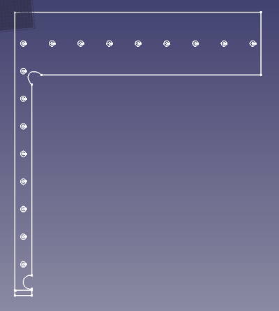 Just some more data needed to be added to the spreadsheet here: Ellipsoid dimensions for the XY-zero cutout, tool-length sensor, and the fence’s witdh on the Y-axis. Its dimensions on the X-axis were predefined by the machine’s travel area already.
Drawing the fence was easy because I could use the “link edge” tool to import positions of lines from other sketches. The fence is an own job with an own physical part on the CNC, and it is only being cut on the “top side”.
Planning phase: CAM
Now came the differcult part: Instead of three jobs as indicated above, I actually needed six. This is, because the CNC has less travel range is smaller than the spoilboard’s dimensions. I was further planning with stocks that already have the correct outline dimensions so I could fit them on the machine.
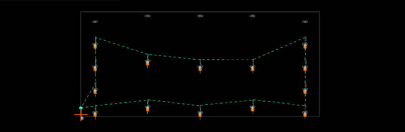
The first part of this job was creating sinks and holes for the lower end of the spoilboard mounts. I set the Zero at the very bottom-left of the machine (X0, Y-max) so I could be sure that the relative coordinates would fit.
For the upper end cut, topmost hole on the left was used as XY-reference zero created in the previous job. This way, I could clamp the stock more flexibly.
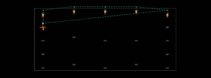
I repeated this approach for the other two jobs.
For the T-nut slot job, I had to mirror the sketch and turn my stock around the Y-axis as the spoilboard’s bottom needed to be machined here. This could be done in CAM as well, but I preferred to quickly jump back into CAD for this task.
For all these jobs, I used a 6mm 2-flute upcut wood bit with a cutter length of 21mm. As these were the first-ever steps I took with a CNC, I planned with very conservative parameters for this tool: S24000rpm, F2800mm/min, Z+=6mm, XY+=85%.
I even ran the first job “in the air” just to make sure I got everything set up right.
Execution
I scratched my head when I finally had the stock on machine bed: where could I clamp it? The sides were occupied by the portal, I have a wall at the rear of the machine… So would it be sufficient to only clamp it on the front? And as I was cutting all the way through, should I add another spoilboard below my spoilboard so that I won’t accidentally cut into the machine bed?
I decided that these objections are justified and waited until the weekend was over so I could buy some scrap wood and more double-sided tape.
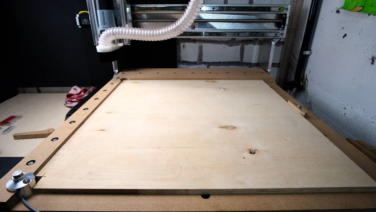
This is how I clamped: Standard C-clamps at the bottom, double-sided tape at the top. Worked very well.
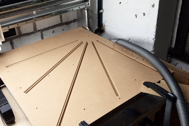
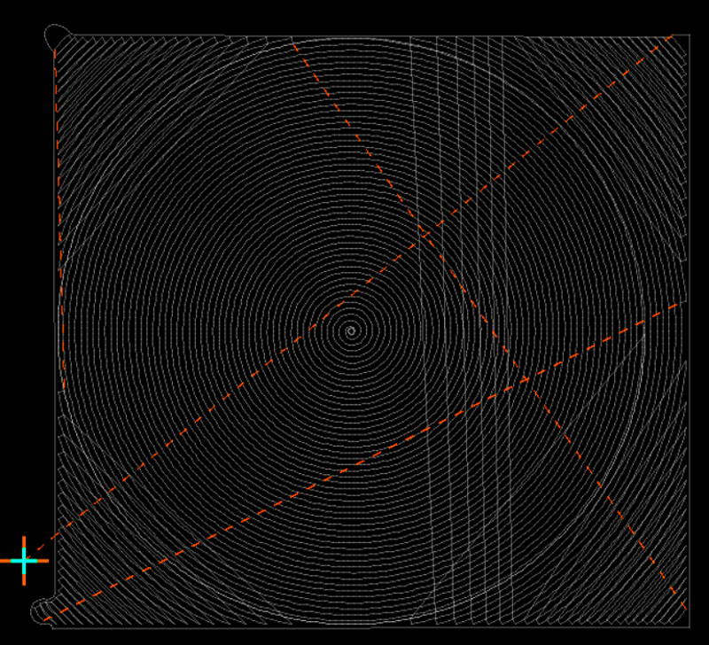
Before finally mounting the frame to the spoilboard, I leveled it with a “spiral” strategy. It was enough to cut Z=0.3mm. I used a 14mm face-mill cutter at a speed as low as S=5500rpm. This job took a long time, almost 30 minutes. The result was a surface as smooth as the original stock’s.
Assessment
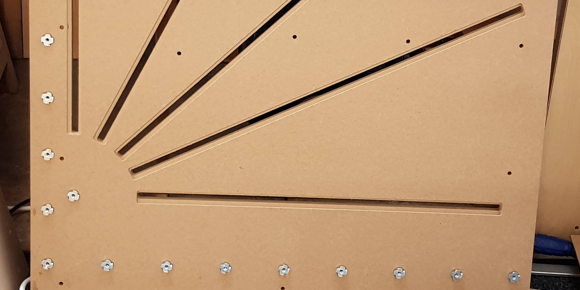
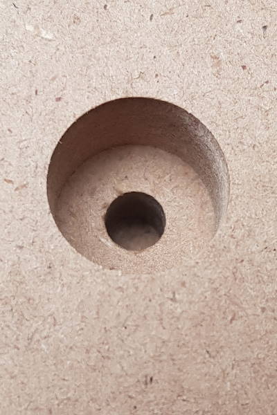 Luckily, in the end it all worked out. Look how clean the cut is! Seems like MDF and sharp endmills are good friends. Note: MDF really needs a good dust collection as it will generate breathtaking amounts of dust when machined.
I’m quite happy with the overall job quality. Every single mount point to machine bed and fence fits OK and the tool-length sensor sits snugly in its cutout.
There are two things to criticize: The endmill I used is very loud and emits an uncomfortable shrieking noise that I even devoted a blog post to. Second, in my CAM tool, I didn’t care enough about milling direction. This way, the CAM decided to do one pass in conventional milling, another one in climb milling direction (it was a full slot as wide as the tool, so for the CAM it’s both climb milling, just the “side” of tool engagement changes). The difference is a very small but noticeable ridge on the fence’s edge.
With this spoilboard, I can process sheets as big as 620mm x 620mm now!
Well, one deficiency left is the tool-length sensor. It protrudes into the working area which is a problem when I want to machine large stocks and have tool changes planned: In this case, I’m using macros for measuring tool length which is why I don’t want to remove the sensor. As an iteration, I could rework the fence so it fully encloses the sensor.
Maybe.
Later.