Aluminiumverbundmaterial
Experimente mit Dibond
Ein Freund von mir gründet gerade eine Unternehmung. Er wollte etwas haben, was er seinen Kunden geben kann, etwas, an das sie sich erinnern würden und so erneut seine Dienste in Anspruch nehmen würden. Es sollte nicht der Standard-Kugelschreiber oder die Tasse sein. Sondern etwas, das etwas näher an dem dran ist, was er selbst tut. Irgendwas metallisches. Vielleicht eine Visitenkarte aus Metall, mit dreidimsionalen Touch. Etwas Graviertes.
Als ich passende Materialien recherchierte, stieß ich auf Aluminiumverbundplatten. Dies sind Sandwichplatten, die einen Kern aus Polyethylen besitzen, welcher auf beiden Seiten mit dünnen Aluminiumblechen kaschiert sind. Solche Platten sind bekannt unter den Markennamen Dibond®, Dilite®, Alcubond® etc. und werden blank oder beschichtet, lackiert oder sogar mit strukturierter Oberfläche angeboten.
“Der PE-Kern ist schwarz durchgefärbt, also könnte es sich prima für Gravurarbeiten eignen”, dachte ich. Also habe ich ein paar Muster bestellt und sie meinem Freund gezeigt. Er war völlig aus dem Häuschen. Und so begann es.
Der Untersetzer
Wir überlegten, was wir alles mit diesem Material anstellen könnten. Es sollte leicht zu designen sein und nicht zu groß werden, sodass es leicht als Werbegeschenk weitergegeben werden kann.
Ich wusste, dass Alu-Sandwichplatten zu dreidimensionalen Objekten gefaltet werden können (Youtube video link) - Aber das schien uns zu kompliziert für den Anfang. Daher war die nächste Idee:
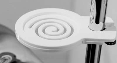
Untersetzer gravieren. Rund oder quadratisch mit abgerundeten Ecken, sogar besondere Formen sind möglich.
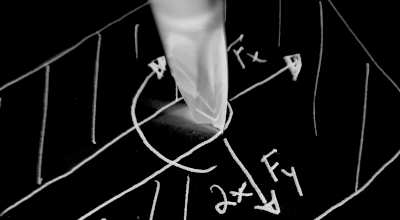
Ich begann, ein paar meiner Gravurfräser für ein paar Experimente auf das Material loszulassen. Die Qualität sah OK aus, war aber noch lange nicht perfekt. Die Aluminiumschicht neigt dazu, zu verschmieren und möchte dem Fräser aus dem Weg gehen, also drückt es sich beim Eintauchen (90°) in das weichere Polyethylen ein und benötigt so höhere Gravurtiefen als die Blechdicke allein vermuten lassen würde.
Der Freund von mir meinte jedoch, ich solle es einfach weiter probieren. Und so bestellte ich ein paar Platten und setzte die Experimente fort.
Fräser, Vorschübe, Drehzahl
Da die Untersetzer filigrane Teile kleiner als 100x100mm sind, nutze ich kleine Fräser:
| VHM-Fräser | Schneiden | ⌀ | Drehzahl | Vorschub XY | Vorschub Z | Z+ |
|---|---|---|---|---|---|---|
| [mm] | [RPM] | [mm/min] | [mm] | [mm] | ||
| Acrylfräser 30° upcut | 1 | 2 | 24000 | 1600 | 800 | 3 |
| Gravierfräser 90° | 1 | 6 | 24000 | 1000 | 500 | 1.5 |
Die Werte mögen für die Aluminiumbearbeitung zu aggressiv sein, ich muss aber einen Mindestvorschub einhalten um den PE-Kern des Plattenmaterials nicht aufzuschmelzen. Die Späne sehen jedenfalls gut aus - kurz und dick. Mit diesen Werten gibt Zerspanobert beim Fräsen eine ruhiges, summendes Geräusch von sich.
Das erste Teil
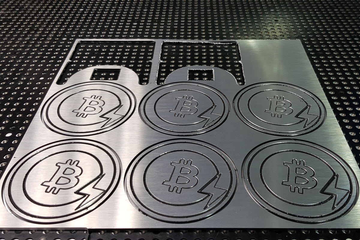
Ich habe zuerst den Halter für die Untersetzer gefertigt. Er besteht aus vier Teilen, die einfach zusammengesteckt werden können. Sie müssen nicht geklebt werden, da ich eine Übergangspassung gewählt habe. Ich verwende einen Anschlag als Orientierung für den XY-Nullpunkt des Werkstücks, da ich beidseitig fräsen möchte. Auf diese Weise kann ich die Ausschnitte in einem letzten Schritt anbringen und den Vakuumdruck auf meinem Tisch bis zu diesem letzten Schritt aufrechterhalten. Außerdem wollte ich vermeiden, dass ich die Teile manuell nachbearbeiten muss.
Der erste Versuch war miserabel - die vorderen und hinteren Fräsbahnen waren nicht perfekt ausgerichtet. Schon ein paar Zehntelmillimeter Versatz zwischen Vorder- und Rückseite machen hier einen großen Unterschied, also musste ich die Ursache beheben (Kanten am Anschlag, die ich vorher nicht bemerkt hatte und die ich abschleifen musste) und es erneut versuchen.
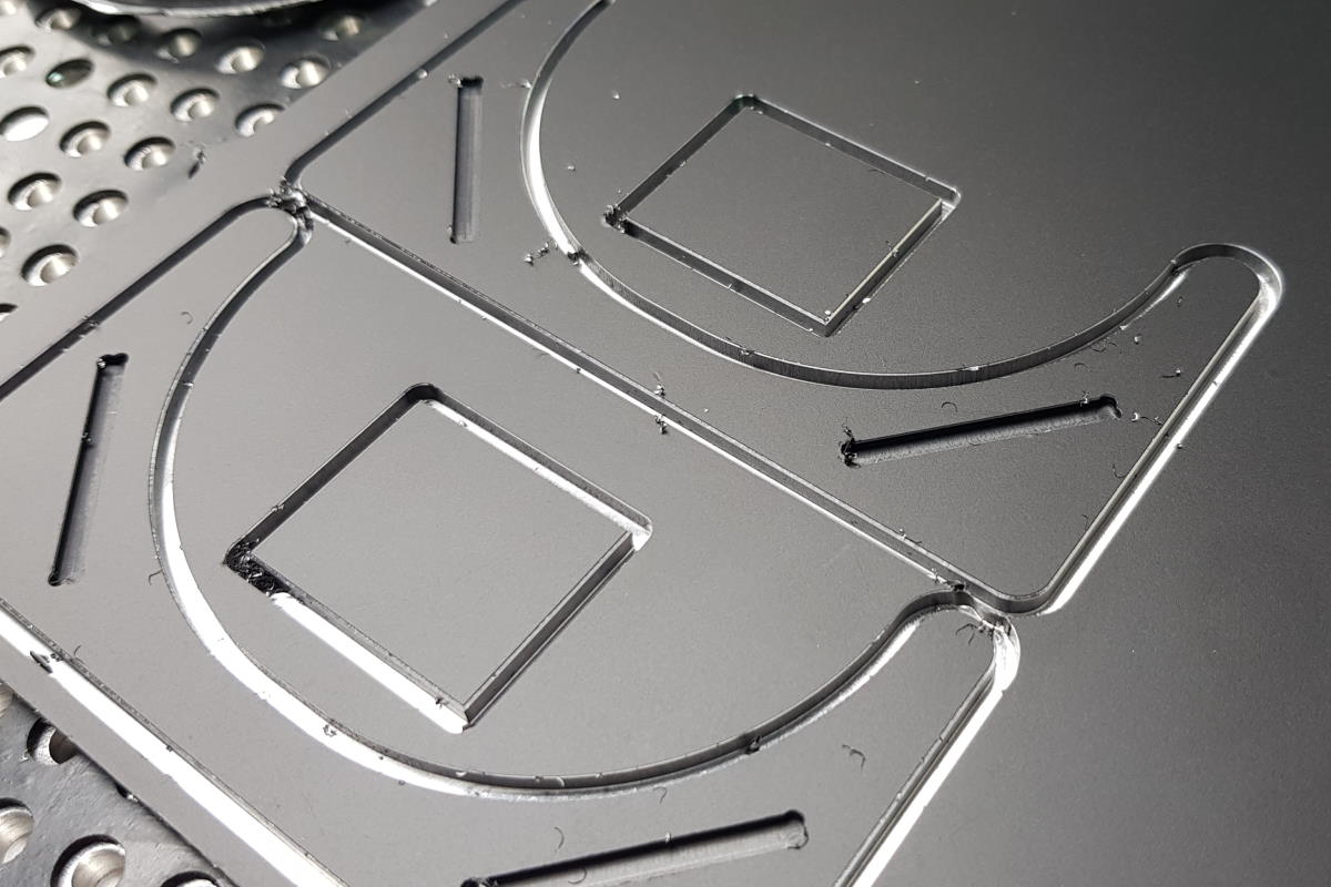
Hier ist das Ergebnis:

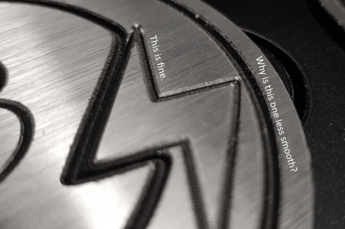
Ich bin ziemlich zufrieden damit. Ich musste keine manuelle Nacharbeit leisten - die Teile sind einfach so aus der CNC gefallen. Die Fasen allerdings, die ich hinzugefügt habe, um dem Material eine glatte Oberfläche zu geben, waren leider von sehr unterschiedlicher Qualität. Während sie auf der “Rückseite” wirklich gut geworden sind, fühlen sie sich auf der Vorderseite viel rauer an. Hier musste das Werkzeug aber auch tiefer eintauchen.
Sechs Stück auf einmal
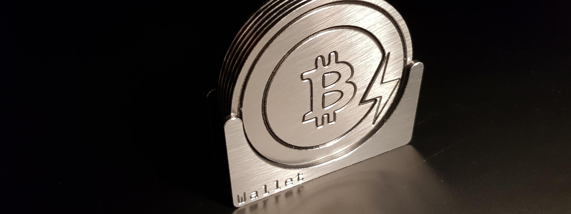
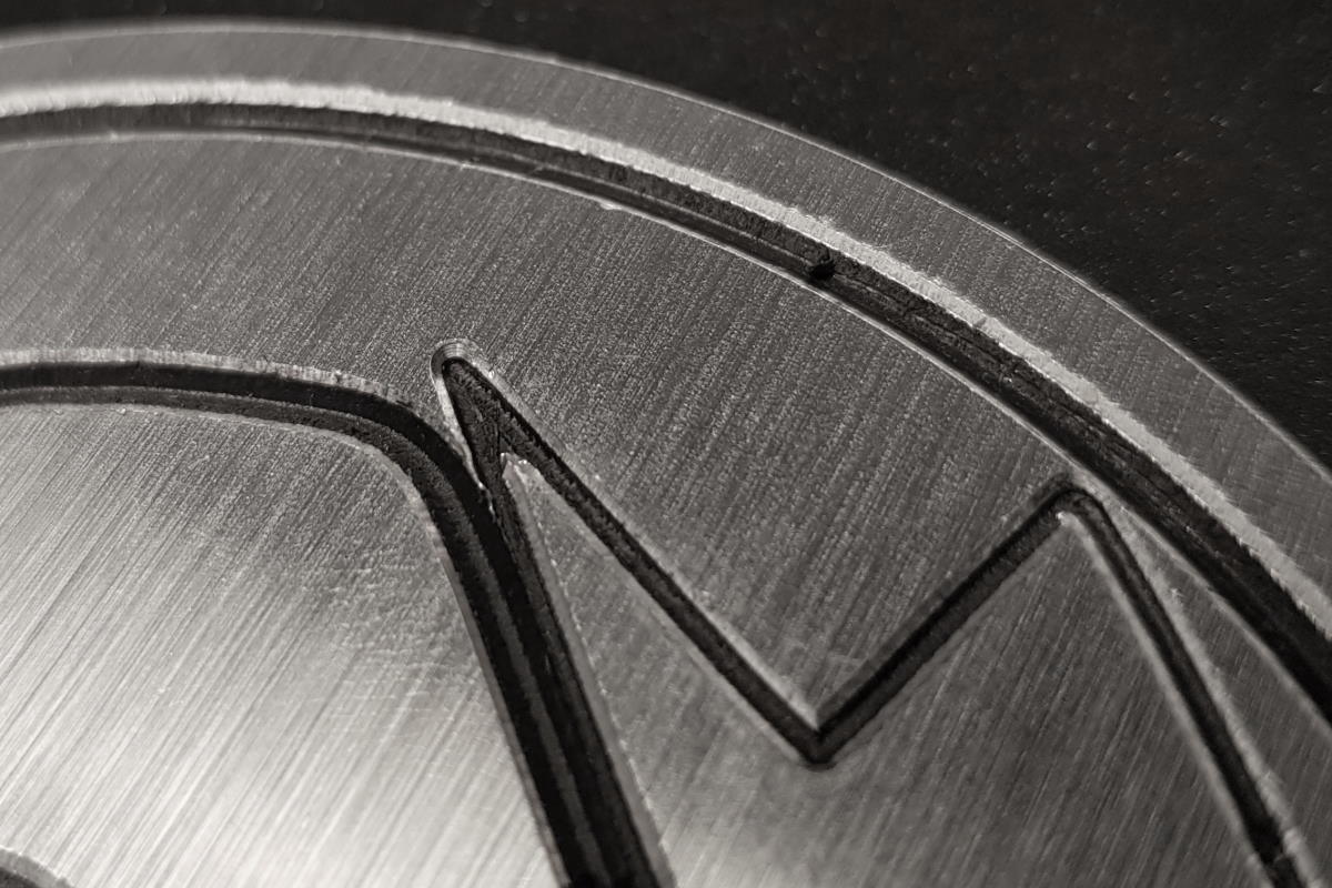
Dann wählte ich ein einfach herzustellendes Logo - das Bitcoin-Blitz-Symbol - und plante einige einfache Gravurpfade, um es zu gravieren. Auch hier habe ich zweiseitig gefräst, so dass das Material nicht vollständig durchtrennt wird, sondern unten eine hauchdünne Schicht Aluminium stehen bleibt, die in einem zweiten Durchgang auf der Unterseite beim Fase fräsen entfernt wird.
Die Maschine brauchte für diesen Job etwa 20min. Leider erwies sich der Anschlag als zu ungenau, um Vorder- und Rückseite mit demselben Nullpunkt passgenau zu fertigen. Der Ausschnitt an der Unterseite wich nur um ein oder zwei Zehntelmillimeter ab, was in meinem Fall die Gesamtabweichung verdoppelt, wenn ich ihn um seine diagonale Achse drehte. Auf diese Weise hatte ein Teil der Kontur meines Untersetzers eine sehr tiefe Fase, während die andere Hälfte überhaupt keine Fase aufwies.
Ich muss bald eine Lösung dafür finden. Bis dahin schleife ich die Kanten von Hand nach. Dann habe ich die restlichen Späne entlang der Gravurwege mit einer Zahnbürste entfernt und das obige Titelfoto aufgenommen.
Qualitätsanalyse
Nachdem ich das Teil genauer untersucht hatte, machte ich die folgenden Beobachtungen:
Alle Teile sehen gleich aus
Das sind doch gute Neuigkeiten. Es bedeutet, dass die Fräser, die ich erstmals bei vhf gekauft habe, scharf geblieben sind und ihr Durchmesser daher konstant war. Ich kann mit den eingestellten Schnittweiten also wahrscheinlich viele weitere Prototypen fertigen. Dibond scheint also ein weniger anspruchsvolles Material zu sein als HPL, wo meine Fräser oft nach zwei Teilen bereits abgenutzt sind und z.B. Passungen klemmen - mehr dazu in diesem Beitrag.
Es bedeutet auch, dass die Maschine keine SChrittverluste oder andere mechanische Probleme hat, und dass mein Klemmbereich eben ist, sodass der 90°-Gravierstichel sehr gleichmäßige Fräsergebnisse liefert. Linien behalten durch die zur Ausrichtung der Z-Achse orthogonale Ebene des Maschinentisches eine einheitliche Breite.
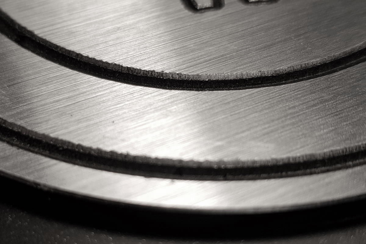
Breitere Gravuren sind qualitativ schlechter als schmalere
Ich bin mir nicht sicher, warum. Da ich noch kein Experte im Umgang mit Dibond bin und keine Ausbildung als Zerspanungsmechaniker vorweisen kann, muss ich raten: Bekommt der Gravierstichel die Späne nicht rechtzeitig aus dem Fräskanal heraus gefördert? Dadurch würde er sie bei der nächsten Drehung erneut erfassen und “durch das Material ziehen”.
Sollte dies der Fall sein, würde ein zusätzlicher Schlichtgang Abhilfe schaffen.
Kantenbrechen ohne vorherige Nutfräsung ergibt rauere Schnittkanten
Hier könnte ich es mit demselben Problem wie oben zu tun haben. Ich probiere es mal mit einem zusätzlichen Schlichtgang aus und schaue, ob es dann besser wird. Update: Tiefgehendere Analyse hierzu in diesem Beitrag Eine weitere Alternative wäre, mit Vorschub und Drehzahl herumzuprobieren um das Optimum herauszufinden. Dafür benötige ich aber erst einmal frisches Material 😅
Zweiseitiger Bearbeitung? Werkstückposition präzise festlegen!
Offensichtlich war ich nicht in der Lage, die Position des Werkstückes nach dem Umdrehen auf die Rückseite mit Hilfe eines Anschlags genau genug festzulegen. Hier reichen ein paar Zehntelmillimeter Abweichung und die Sandwichplatte ist Schrott.
Lösungsansätze:
- Einen
Job00einfügen, der Locatorlöcher (Positionsgeber) mit5.04mmDurchmesser in einen Teil des Werkstücks einbringt, was später ein Abfallstück wird. Wenn ich sie symmetrisch platziere und diese Löcher ebenfalls im Frästisch fertige, so kann ich Passstifte einbringen, die mir die genaue Werkstückpositionierung beim Drehen auf die Rückseite sicherstellen. - Die Position des Anschlags überprüfen und sicherstellen, dass das Rohteil genau rechtwinklig und ohne Lichtspalt dort anliegt.
- Ich könnte auch durchfräsen und die scharfen Kanten auf der Rückseite an einem Frästisch von Hand brechen. Da ich allerdings a) keine Frästisch besitze, b) meine Werkstücke oft sehr klein sind und c) Ich manuelle Nacharbeit verabscheue, wird dies wohl eine Rückfallebene bleiben für den Fall, dass die beiden obigen Lösungen für mich nicht funktionieren.
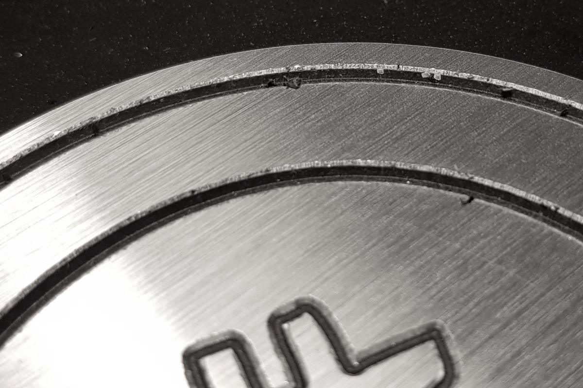
Einige Späne kleben in der Fräsnut fest
Ich habe keine Ahnung, warum. Werden die Späne zu heiß und schmelzen sich in die Polyethylenschicht ein? Ich werde wohl mal mit dem Fräserhersteller telefonieren müssen, um das zu klären.
Zusammenfassung
Alles in Allem kann ich einigermaßen zufrieden sein. Die Maschine ist in der Lage, Dibond und andere Aluminiumverbundmaterialien zu bearbeiten und die Ergebnisse sehen für einen ersten Versuch OK aus. Das Verbundmaterial nutzt die Fräser nicht übermäßig schnell ab und sieht einfach toll aus im Kontrast mit dem schwarzen Kern. Die Späne stören mich allerdings etwas, denn sie haften überall an und mögen ungern abgesaugt werden.
Dennoch. Die Qualität überzeugt mich noch nicht voll. Ich werde weiter probieren und meinen Fortschritt im Blog dokumentieren.